
The flag animation has one servo, one stepper motor and one LED. It uses the animator 5v mono board. The 5v mono board does not have a sd card. Mp3 files are stored directly on the raspberry pi pico flash and outputs left channel sound only.
The stepper motor is driven by another board which also controls the LED.
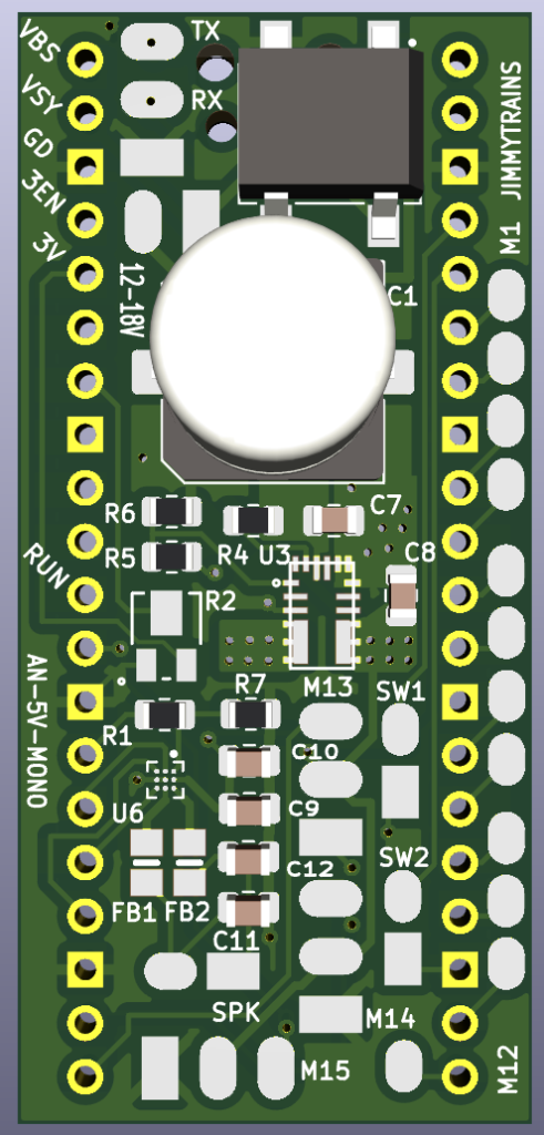
Animator board setup
Put UTF file on new pico using 8.2.10 version. Then when it reboots install the program files on the circuit python drive.
Pre assembly
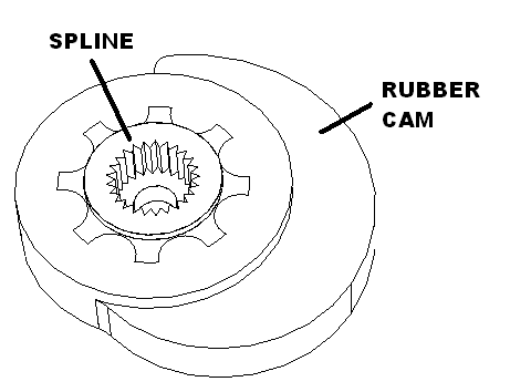
Apply glue to inside of rubber cam, press spline hub into rubber cam as shown.
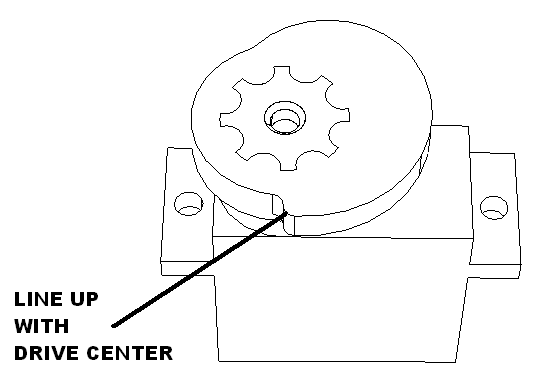
Plug servo into animator board. Attach drive cam to servo using provided screw and orient roughly as shown. Set aside.
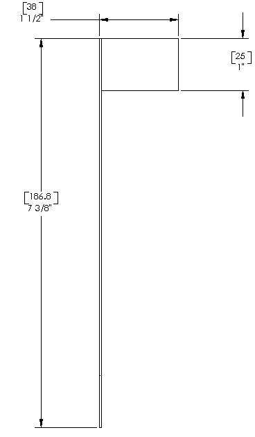
Cut 0.039″ rod to 7 3/8 inches.
Using flag fixture set down blue tape with edge to the bottom. Set rod on top and fold tape around.
Move to cutting area and trim blue tape to 7/8 inches.
Apply printed paper flag around this and trim.
Set aside until final test.
Animator wiring
Attach the animator board to the kite electrical fixture using one animator clamp and one M2.3 X 6 screw as shown.
Attach the stepper board upside down to the flag electrical fixture chassis using two M2.3 X 6 screws as shown.

Switch connections
Cut two brown 26 gauge gauge wires to 10″ lengths. Solder to a switch then shrink wrap. Repeat for a blue wire. Then solder the switch harnesses to the animator board using the following table.
Then solder the switch harnesses to the animator board using the following table.
| Function | Connect to | Wire length/gauge/color/an dir |
| Left switch | SW1 to pushbutton | 10″ / 26 / BRN / left |
| Right switch | SW2 to pushbutton | 10″ / 26 / BLU / left |
Servo connections
Cut servo female harness to 4″. Then solder the switch harnesses to the animator board using the following table.
| Function | Connect from then to | Wire length/gauge/color/dir |
| Servo 1 | M13 to Female servo harness | 4″ / 26 / Varies / right |
Power connections
Cut two black 26 gauge gauge wires to 10″ lengths. Then solder to the animator board using the following table.
| Function | Connect to | Wire length/gauge/color/an dir |
| Accessory Power 12-18 V AC/DC | 12-18V | 10″ / 26 / BLK / down |
Stepper board connections
Twist black, blue, red, brown and yellow 30 gauge wire and cut to 3″ lengths. Then solder from the animator board to the back side of the stepper board using the following table.
| Function | Connect from to | Wire length/gauge/color/an dir |
| Stepper coil A1 | M1 to pin 1 Stepper | 3″ / 30 / BLK / left |
| Stepper coil A2 | M2 to pin 2 Stepper | 3″ / 30 / BLU / left |
| Stepper coil B1 | M3 to pin 3 Stepper | 3″ / 30 / RED / left |
| Stepper coil B2 | M4 to pin 4 Stepper | 3″ / 30 / BRN / left |
| LED stepper board | M5 to pin 5 Stepper | 3″ / 30 / YEL / left |
Cut blue and brown 26 gauge gauge wire and cut to 5″ lengths. Then solder from the animator board to the back side of the stepper board using the following table.
| Function | Connect from to | Wire length/gauge/color/an dir |
| Stepper GND | M15 GND to Stepper GND | 5″ / 30 / BRN / down |
| Stepper 5 volts | M15 Vcc to Stepper 5V | 5″ / 30 / BLU / down |
LED connections
Cut LED leads. Short one is negative cut below tab point. Long one is positive cut above tab point.
Cut orange and black 30 gauge gauge wire to 5″ lengths. Solder black one to the short lead and orange one the the long lead.
Put small piece of painters tab on LED cylinder. Insert in the LED holder as shown. Route wires through hole and bend LED leads to the left.
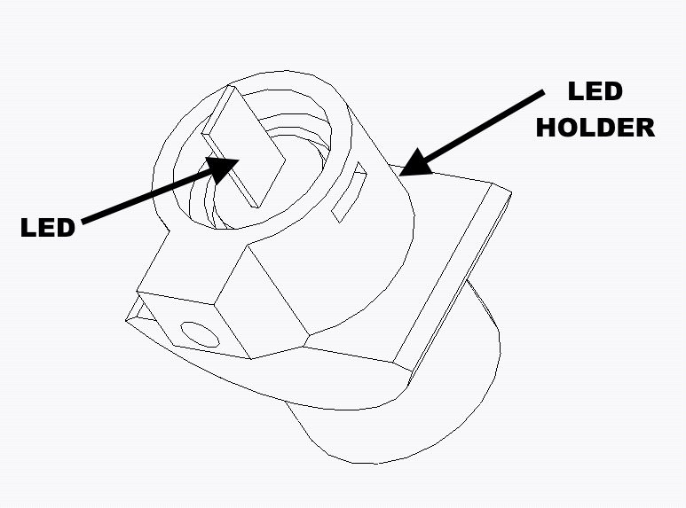
Cut a 150 ohm resistor short on one side. Solder to Vcc on the stepper board. Glue the resistor down with a spot of super glue. Let dry.
Then solder back side of the stepper board using the following table.
| Function | Connect to | Wire length/gauge/color/an dir |
| Stepper output | Stepper output pin 5 | 5″ / 30 / BLK / down |
| Stepper 5 volts | Resistor | 5″ / 30 / ORG / down |
Install LED assembly into the chassis as shown using one M2.3 X 8 screw make sure it is pointed to the flag.
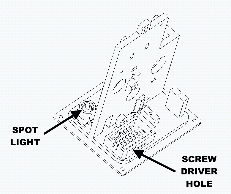
Mount animator board
Attach the animator board to the flag chassis using one animator clamp and one M2.3 X 6 screw as shown. Attach the stepper board to the flag chassis using two M2.3 X 6 screws.
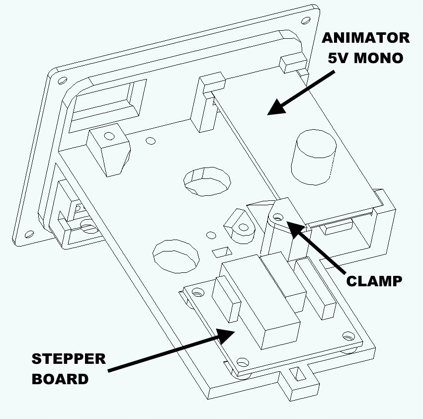
Speaker connections
Cut one brown wire and one blue wire to 6″. Then solder wires to speaker as shown.
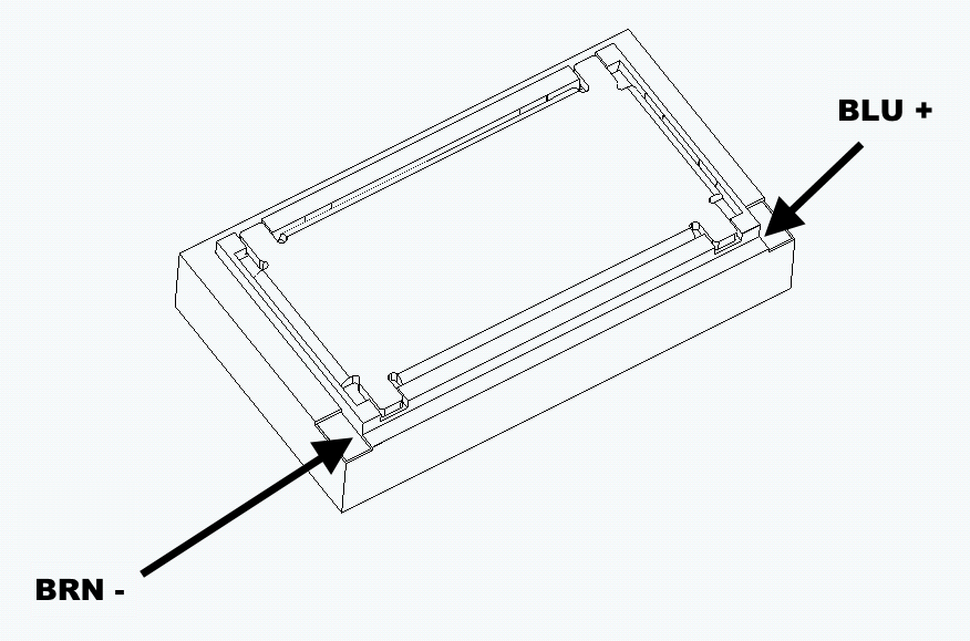
Route speaker wires through speaker wire hole, press speaker in.
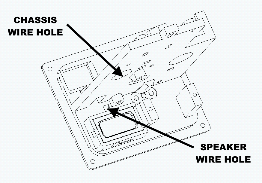
Then solder the animator board using the following table.
| Function | Connect to | Wire length/gauge/color/dir |
| Mono speaker | SPK | 6″ / 26 / BRN-BLU+R |
Mechanical assembly
Insert M3 X 18 pin into flag chassis as shown.
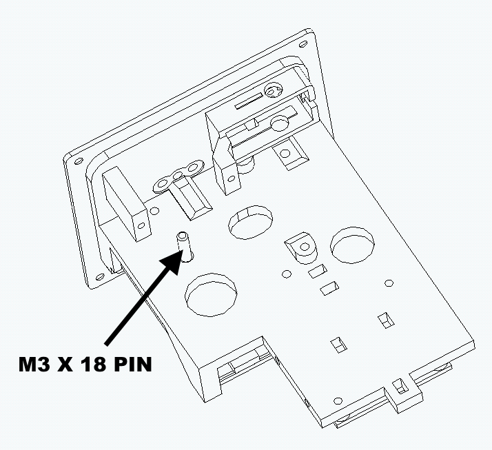
Route the servo harness through the hole in flag chassis.
Install stepper motor as shown with two M2.6 X 8 screws do not fully tighten.
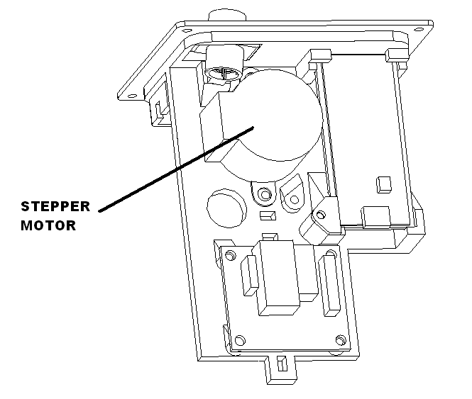
Install the flag pole to the flag chassis using two M2.3 x 8 screws as shown. From this point be very careful not to bend the flag pole. It is very delicate.
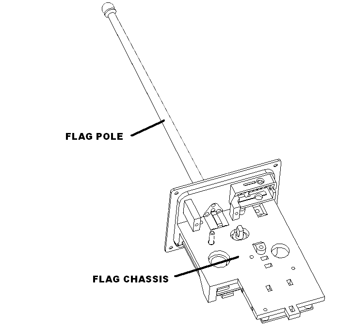
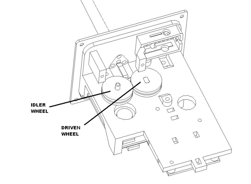
Place rubber idler wheel on pin with flange down. Place driven wheel on stepper motor shaft flange down. Press steeper motor against idler and tighten screws.
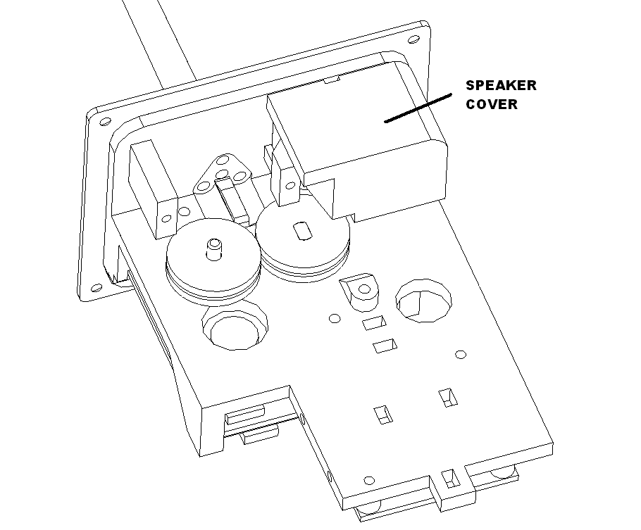
Snap speaker cover on while being careful wires do not get pinched.
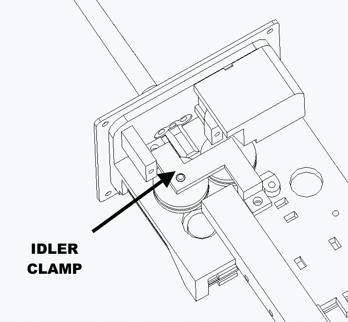
Install idler clamp with two M2.6 X 8 screws as shown.
Snap together the rod guard base and cover as shown.
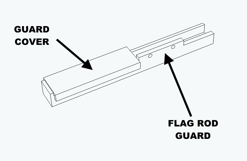
Attach the flag rod guard to the flag chassis with two M2.6 X 8 screws.

Install flag drive with screws provided with servo.
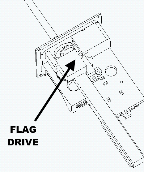
Carefully insert flag into flag pole assembly. Power up the animator flag and confirm that the flag lowers to the bottom position.
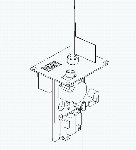
Calibrate flag waving
Using the menu buttons active the flag waving calibration. Adjust until it starts waving and add 5 more steps to it. Press and hold right button until you hear all changes complete.
Package the flag
Laser cut the bottom insert, mid insert, top insert and presentation insert.
Bend the mid insert as shown
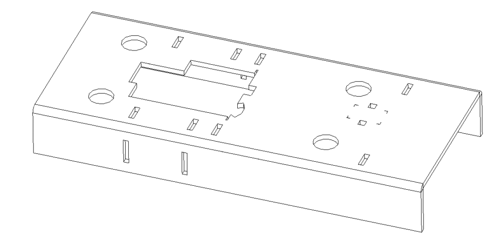
Bend the bottom insert as shown and insert in the top insert.
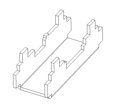
Place the flag into the cavity in the top insert as shown. Fold accordion paper into four layers, twist tie the flag pole down. Set assembly into box.
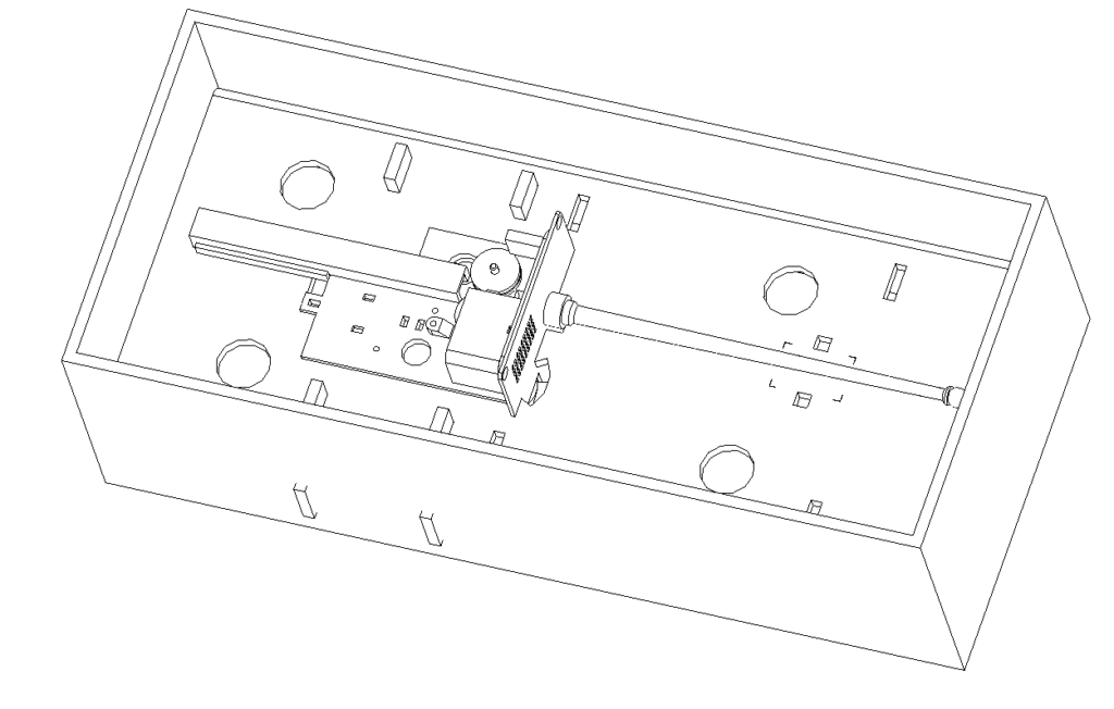
Bend the top insert as shown and insert into the slots in the on the right.
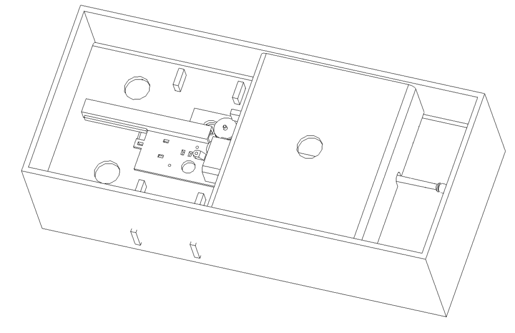
Print out outer box label, presentation insert label and envelope label. Apply label to the presentation insert. Set in box Apply envelope label to envelope. Put flag into envelope with spare label. Seal just at the point. Put in box. Close box and apply product label.