
Container car body assembly
Preassembly
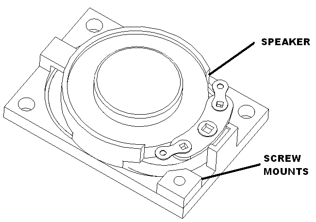
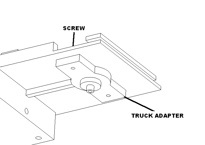
Glue screw mounts to speakers as shown. Set aside to dry.
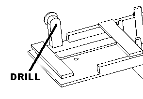
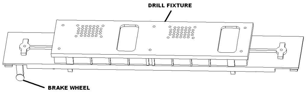
Replace brake wheel with a metal one. Drill out the plastic one with a #52 drill bit. Then glue in a metal one. Set aside to dry.
Replace wires on Atlas truck with flexible red wires cut to 10 inches.
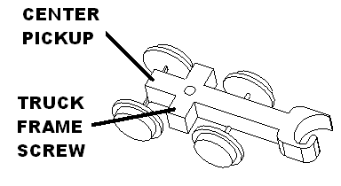
Mark ends of one of them with black marker. Make solder loop and apply xxx shrink wrap. Connect to truck frame by unscrew lower screw. Once attached glue shrink wrap to truck.
Attach other one to center rail roller. Apply xxx shrink wrap.
Hole drilling
Remove trucks from container car gently prying up the pressed in studs.
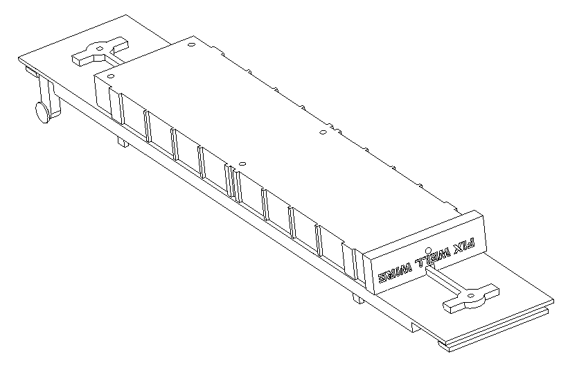
Drill holes for the truck adapters using WELL FIX and 1/8 inch drill bit.
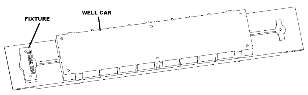
Drill mount holes and speakers holes using drill fixture and 1/8 inch drill bit.
Drill wire hole into the ends of the cars using 1/8 inch drill bit.
Mount trucks
Attach truck mount with two M2.3 X 8 pan head screws.
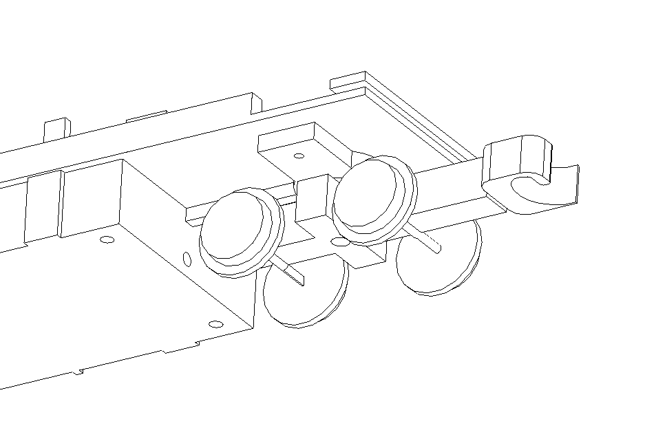
Feed truck wires into container car. Attach trucks using the screws provided with the trucks.
Container car connections
Join truck wires with female JST 2.0 connector. See table for length.
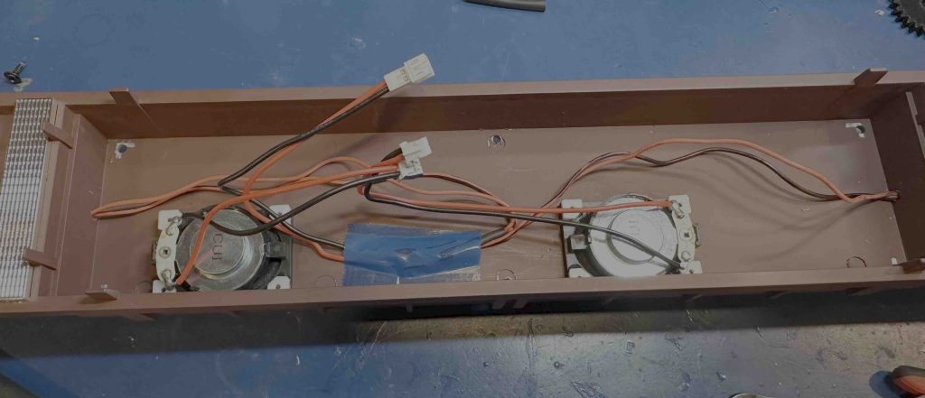
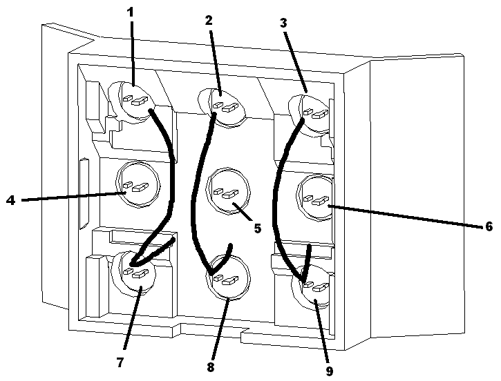
Mark the left speaker connections with black marker. Solder harnesses to speakers crossing over the driver.
Turn the trucks back and forth and confirm adequate wire is exposed.
Cut the truck power wires 7″ from each car body end.
Slip 1″ shrink wrap onto the power connector wires. Connect the truck wires to the power cable with the black going to the truck frame connection and the red to the center roller. Shrink wrap all connections.
| Connect to | Wire length/gauge/color/dir/type |
| LEFT SPK | 3″ / 26 / BLK, RED / right / male |
| RIGHT SPK | 5″ / 26 / BLK, RED / left / male |
| POWER | 5″ / 26 / BLK, RED / right / female |
Tape truck wires out of the way with blue tape. Bend all connectors to the right as shown.
Board programming
Using raspberry pi image write out sd cards. Load the software and update the visudo file using
- sudo visudo
- cameratrain ALL=(ALL) NOPASSWD: /sbin/reboot
- cameratrain ALL=(ALL) NOPASSWD: /usr/bin/nmcli
Board connections
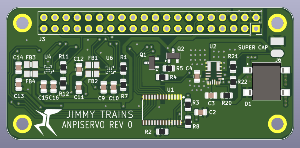
Solder cap on board.
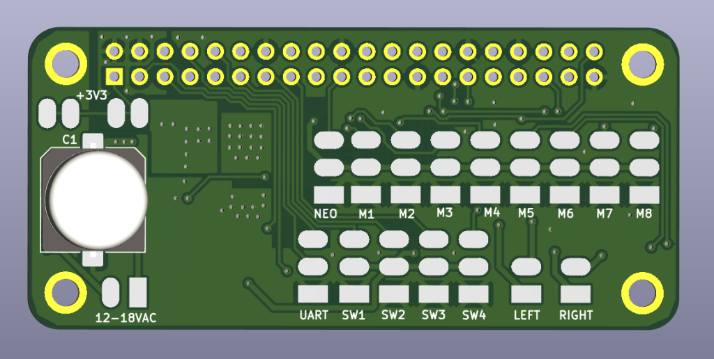
Wire the board as follows.
| Connect to | Wire length/gauge/color/dir/type |
| NEO | 6″ / 26 / Varies / right / female |
| M1 | 2″ / 26 / Varies / left / female |
| M2 | 4″ / 26 / Varies / right / female |
| M3 | 4″ / 26 / Varies / right / female |
| M4 | 4″ / 26 / Varies / right / female |
| 12-18VAC | 3″ / 26 / Varies / right / male |
| LEFT speaker | 2.5″ / 26 / Varies / right / female |
| RIGHT right (mark this with black marker) | 2.5″ / 26 / Varies / right / female |
| SW1 left switch | 7″ / 30 / black / right / NA |
| SW2 right switch | 7″ / 30 / blue / right / NA |
Board mounting
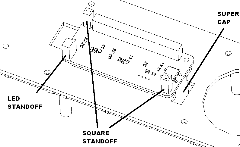
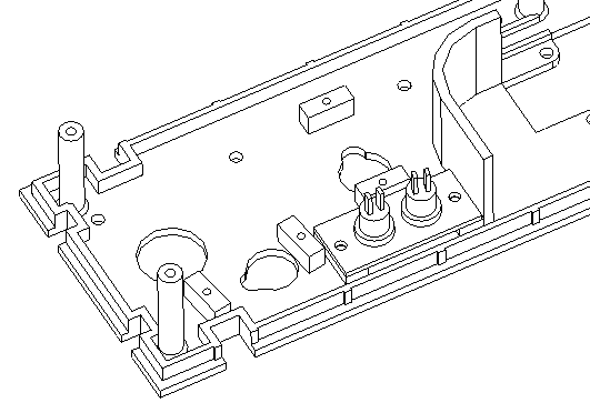
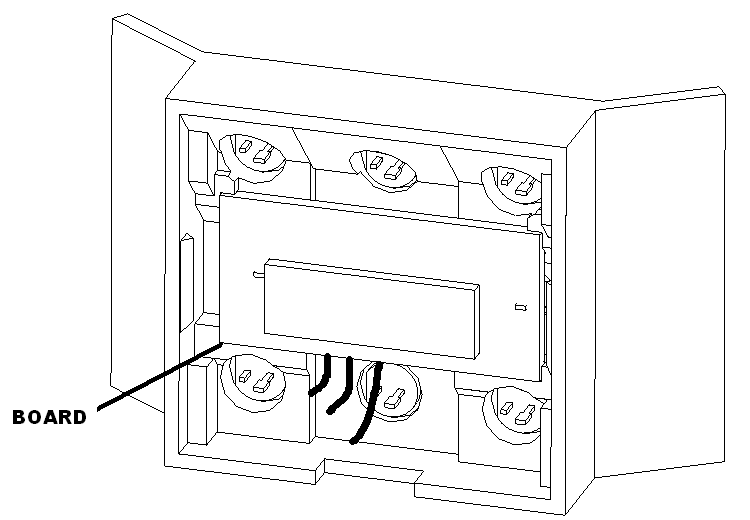
Attach board to chassis using 3 M2.3X8 screws and one LED standoff and two square standoffs as shown.
Bend legs of super cap. Apply xxx shrink wrap to negative lead, apply xxx shrink wrap to the positive lead. Bend wires as needed and solder super cap on backside.
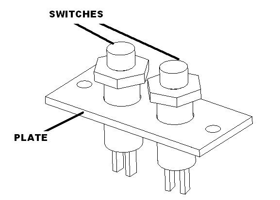
Attach switch plate to main chassis using 2 M2.3 x 6 screws. Solder black wires to front switch and blue wires to the back switch.
LED bar assembly
Preassembly
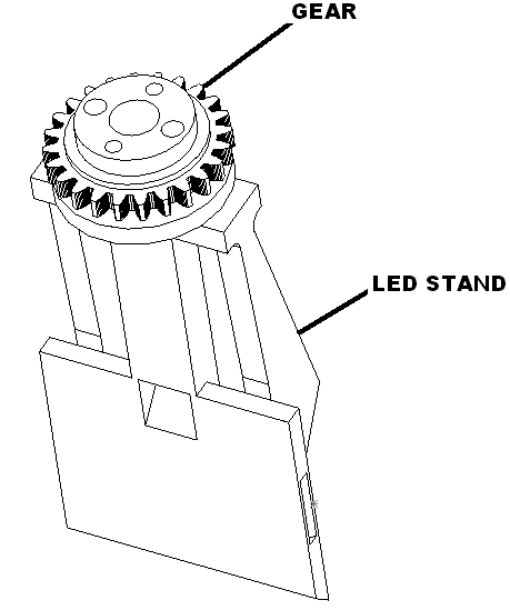
Glue LED bar onto LED stand as shown using two #4 screws. Set aside to dry.
Assembly
Route male three wire harness trough the bottom of the LED stand. Solder the wire harness to city lights neo-6 board using the following table.
| Function | Connect to | Twisted Cable Color |
| +5V | 5V (top pad) | RED |
| Signal | Signal (middle pad) | YEL |
| GND | GND (bottom pad) | BRN |
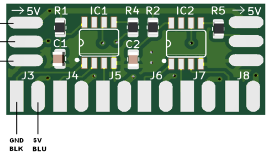
Clip LEDs as shown below. Solder blue and black wires to LEDs. Solder to neo-6 board using the following table.
| LED number | Connect to | Length / LED Color |
| 1, 7 | J3 | 2″, 3″ / WHT |
| 2, 8 | J4 | 2″, 3″ / WHT |
| 3, 9 | J5 | 2″, 3″ / WHT |
| 4 | J6 | 3″ / BLU |
| 5 | J7 | 3″ / GRN |
| 6 | J8 | 3″ / RED |
Test lights.
Glue LED in the following locations: white in 1, 7, 2, 8, 3, 9. Install blue in 4, green in 5, and red in 6.
Install board as shown with wires coming out the bottom.
Snap assembly together. Set aside.
Camera rotation assembly
Preassembly
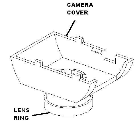
Glue lens ring to camera cover set aside to dry.
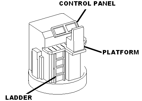
Glue ladder, control panel and chair assembly onto camera cover. Set aside to dry.
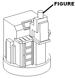
Glue figure onto chair on camera cover. Set aside to dry.
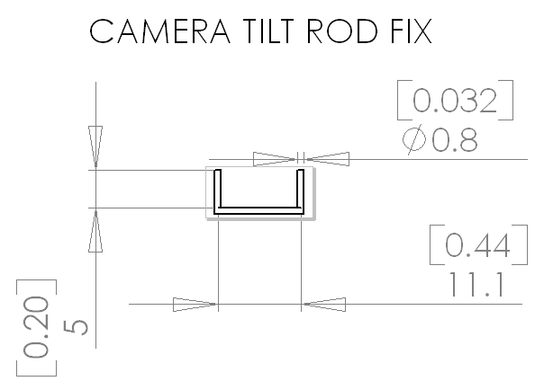
Bend 0.032in wire as shown.
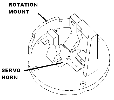
Cut servo horn to the three hole mark as shown. Sand servo horn and clean. Glue to rotation assembly with smaller arm to the right using gel superglue as shown and set with accelerator. Set aside to dry.
Assembly
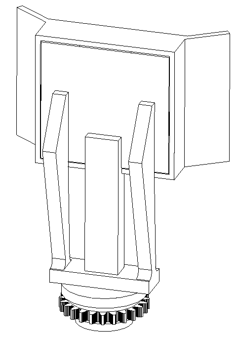
Attach servo to rotation servo mount as shown.
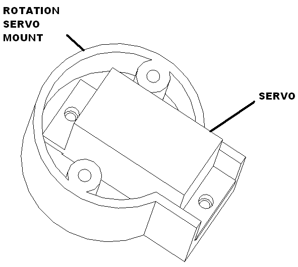
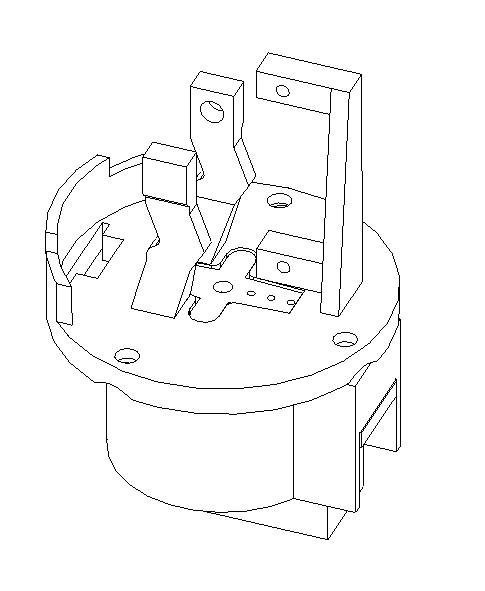
Power up the rotation servo, set to 90 degrees. Install to the rotation mount as shown.
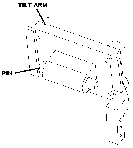
Insert pin into tilt arm as shown.
Install camera using M2.3 X 8 pan head screws.
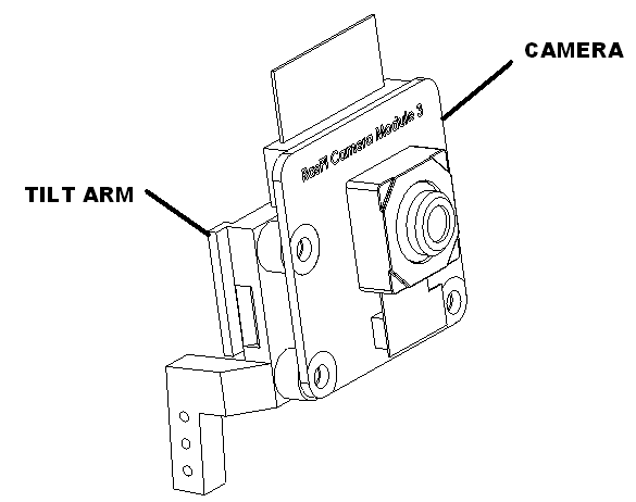
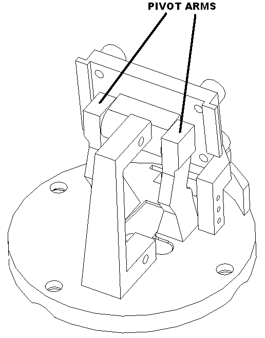
Install camera cable into camera. Bend top of cable and thread into slot in rotation mount. Install tilt arm into rotation mount by gently spreading the pivot arms to engage the pin into the arms.
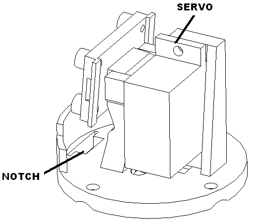
Install servo motor as shown. Route wires in front notched hole.
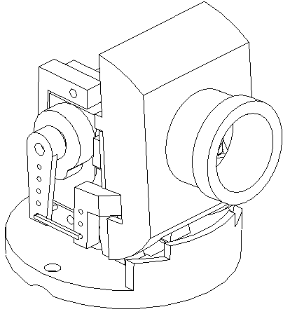
Power up the rotation servo, set to 90 degrees. Install horn and rod with camera point down to lowest point.

Bend cable as shown with servo all the way down.
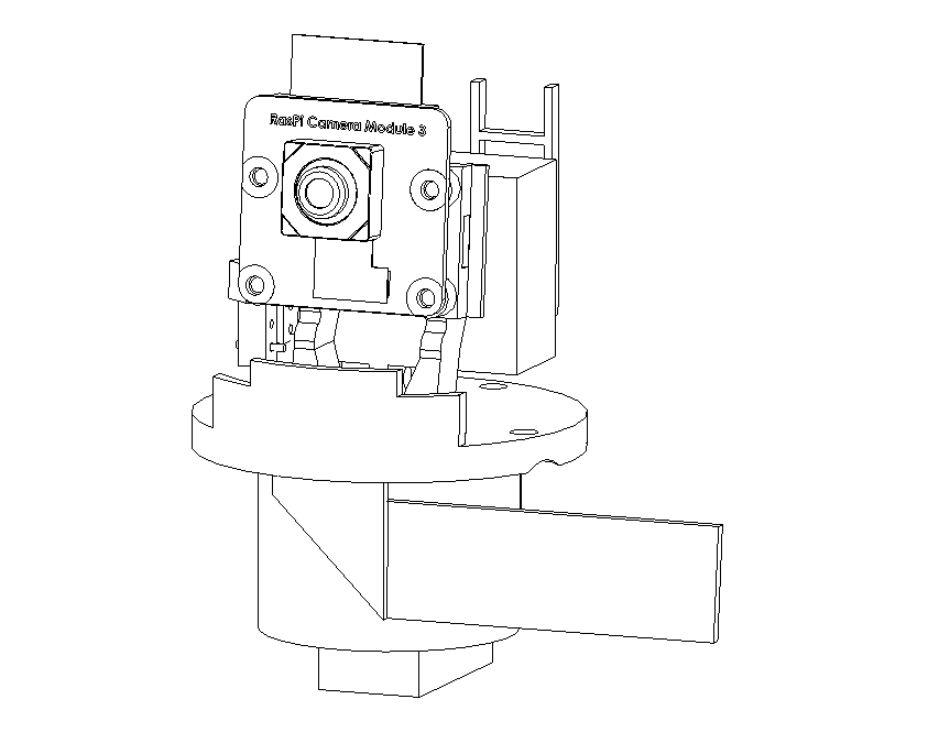
Snap camera cover on as shown with notch toward bottom.
Install cover with 3 M2.3 x 8 screws. Set aside.
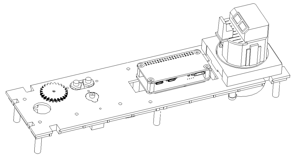
Main chassis assembly
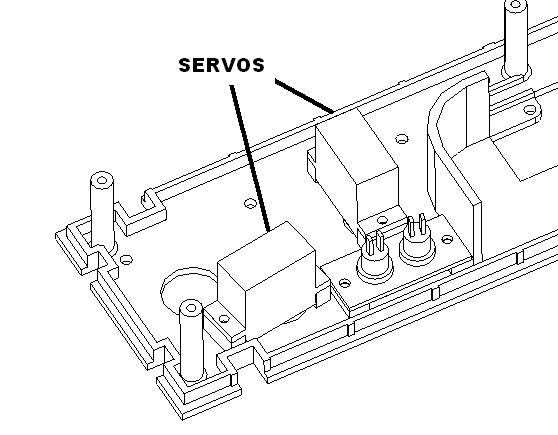
Attach servo motors to chassis assembly.
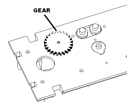
Attach light bar gear.
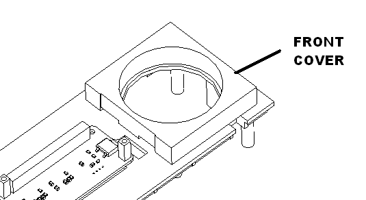
Attach front cover using 4 M2.3 x 8 screws. Do not fully tighten yet.
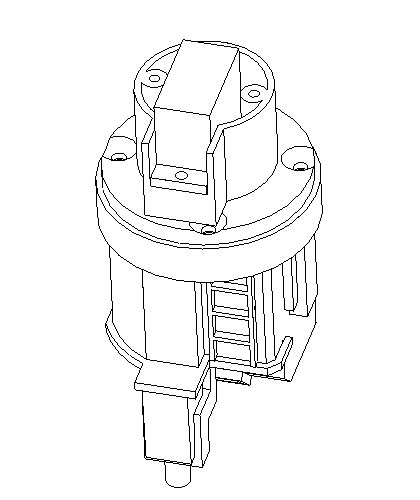
Insert camera rotation assembly into hole as shown.

Place the wire channel over this carfully routing the cable into the channel. Attach rotation assembly to the wire channel with two M2.3 X 8 screws. Then attach the wire channel to the chassis. Be careful not to damage the camera man.
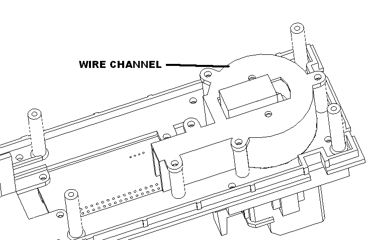
Route the camera cable to the top of the assembly. Carefully plug into the pi sbc and latch the connector. Insert the board into the animator board.
Install the rear car cover using 6 M2.3 x 8 screws.

Power up the light bar servo. Set it to 90 degrees. Insert the light bar pointing forward and attach it with its retaining collar and 2 M2.3 x 8 screws.

Plug in all the servos and tywrap the wires as shown.
xxx
Plug in camera car assembly into the container car. Make sure no wires get pinched. Test all the functions. Then attach fasten using 6 M2.3 x 8 screws.
Jump drive
Put the env.txt file on the jump drive. Label it with a sticker.