
Preassembly
If making a panel mount neopico glue the collar onto the neopico cover as shown.
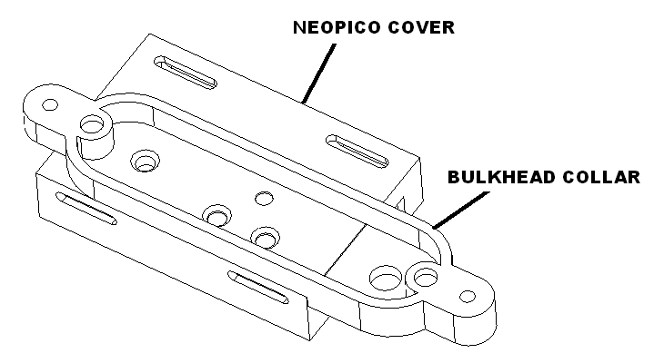
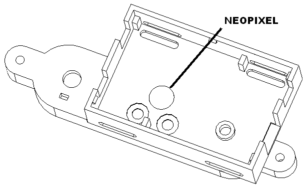
Turn the cover over and solder one neopixel to the cover as shown. Set aside to dry.
Wiring overview
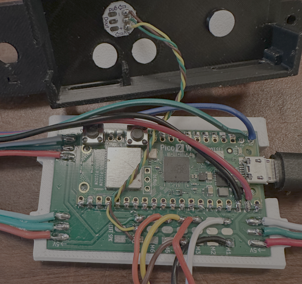
Neopico board
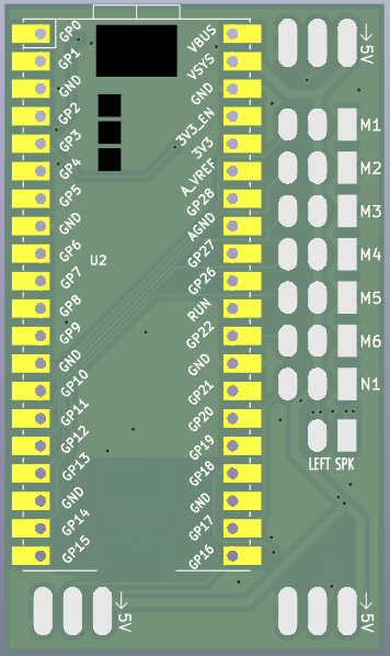
Pico assembly
Rev 0 boards need modifications replace R1, R5, R7 with 300 ohm 805 chip resistor.
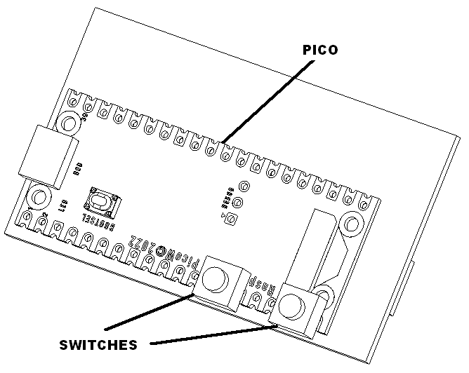
Solder Pico 2W to the board as follows. Solder two switches as shown.
Board connections
Neopixel input
Solder a male neopixel cable to the top left neo pads according to the following table.
| Connect to | Wire Color |
| 5V (pad 1 labeled 5V) | RED |
| Signal (pad 2) | GRN |
| GND (pad 3) | WHT |
Neopixel output
Solder a female neopixel cable to the top right neo pads according to the following table.
| Connect to | Wire Color |
| 5V (pad 1 labeled 5V) | RED |
| Signal (pad 2) | GRN |
| GND (pad 3) | WHT |
Neopico neopixel output
Solder a female neopixel cable to the bottom right neo pads according to the following table.
| Connect to | Wire Color |
| 5V (pad 1 labeled 5V) | RED |
| Signal (pad 2) | GRN |
| GND (pad 3) | WHT |
Switch harness connection left and right
Cut a three pin female cable to xxx inches. Solder this cable to the board using the following table.
| Connect to | Wire Color |
| M1 GND (square pad 1) | BLK or BRN |
| M1 Signal (pad 3) | WHT or YEL |
| M3 Signal (pad 3) | RED |
Switch harness connection 3 and 4
Cut a three pin female cable to xxx inches. Solder this cable to the board using the following table.
| Connect to | Wire Color |
| M4 GND (square pad 1) | BLK or BRN |
| M4 Signal (pad 3) | WHT or YEL |
| M5 Signal (pad 3) | RED |
Neopixel indicator
Cut three 30 gauge wires to 4 inches and twist. Solder this cable to the board and to the neopixel using the following table.
| Connect from board | Connect to neopixel | Wire Color |
| N1 GND (square pad 1) | GND (pad 3) | BLK or BRN |
| N1 5V (pad 2) | 5V (5V pad 1) | WHT or YEL |
| N1 Signal (pad 3) | Signal (pad 2) | RED |
I2C connections (optional)
Attach female 4 pin cable to the board using the following table.
| Connect from board | Wire Color |
| VSYS (pin 39) | RED |
| GND (pin 28) | BLK |
| SDA (pin 1) | BLU |
| SCL (pin 2) | GRN |
I2C display connections (optional)
Attach male 4 pin cable to the display using the following table.
| Connect from board | Wire Color |
| GND (pin 1) | BLK |
| VCC (pin 2) | RED |
| SCL (pin 3) | GRN |
| SDA (pin 4) | BLU |