
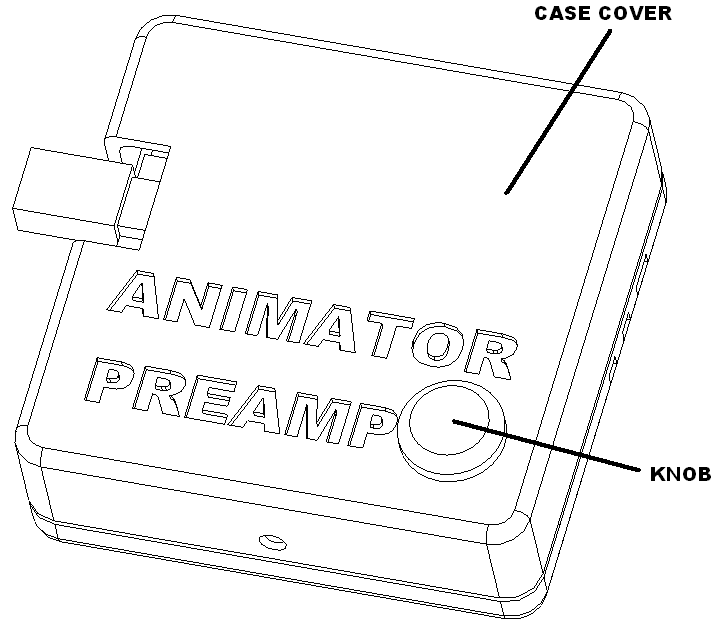
Preassembly
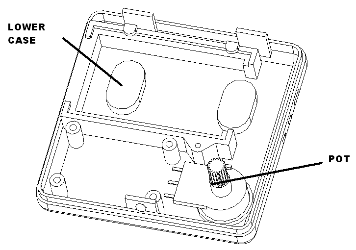
Glue the pot to the lower case as shown. Set aside to dry.
Prepare wires
Cut two black wires 10″ long. Label wire with “12-18 V AC/DC”, 5″ from end.
Cut two brown wires 10″ long, solder and shrink wrap to left switch. Label switch wire with “LEFT SW”, 5″ from end.
Cut two blue wires 10″ long, solder and shrink wrap to right switch. Label switch wire with “RIGHT SW”, 5″ from end.
Cut female end of a servo extension cable 10 10″ retain the male end to make the 8 foot cable. Label neopixel harness with “NEOPIXEL”, 5″ from end.
Route wires
Route the neo pixel cable in the top slot of the lower case, the right switch cable next and then the left switch cable.
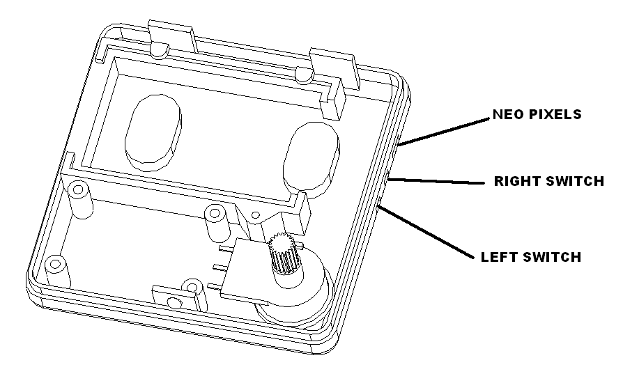
Strip and tin all wires.
Subwoofer assembly
Glue rubber feet to the bottom of the subwoofer case using super glue gel. Set aside to dry.
Cut white and gray wire to 20 inch length. Feed wires through subwoofer bottom and solder white wire to positive and grey wire to negative terminal on speaker.
Stuff fill into the speaker.
Attach woofer to speaker cabinet using 6 number 6 x 3/4″ screws.
Attach bezel to speaker cabinet using 6 number 6 x 1″ screws.
Bar assembly
Cut neopixel strip to 10 led lengths.
Solder male three pin connector to neo pixel strip on the input side. Solder female three pin connector to the output side.
Strip adhesive strip. Apply super glue to the bolt base. Attach the neopixel strip with the male on the left side with the mounting hole up. Set aside to dry in front of a fan.
Snap the cover on.
Bolt assembly 1 bolt
Cut neopixel strip to 1 led lengths.
Solder male three pin connector to neo pixel strip on the input side. Solder female three pin connector to the output side.
Strip adhesive strip. Attach to the bolt base with female to the left and male to the right as shown.
Heat bend a 5mm rod to a bolt shape.
Clamp assembly together with 2 number 7 by 5/8 screws.
Bolt assembly 2 bolt
Cut neopixel strip to 2 led lengths.
Solder male three pin connector to neo pixel strip on the input side. Solder female three pin connector to the output side.
Strip adhesive strip. Attach to the bolt base with female to the left and male to the right as shown.
Heat bend two 5mm rods to a bolt shape.
Clamp assembly together with 3 number 7 by 5/8 screws.
Bolt assembly 3 bolt
Cut neopixel strip to 3 led lengths.
Solder male three pin connector to neo pixel strip on the input side. Solder female three pin connector to the output side.
Strip adhesive strip. Attach to the bolt base with female to the left and male to the right as shown.
Heat bend two 5mm rods to a bolt shape.
Clamp assembly together with 4 number 7 by 5/8 screws.
Tiny animator backside connections
The backside of the board has all the connections for the switches, neopixels, and volume control.

Volume pot
Twist black, blue and orange 30 gauge wire together. Cut to 4″ lengths. Solder to the animator as shown
| Function | Connect to | Wire length/gauge/color/dir |
| Volume pot | RV1 | 4″ / 30 / Varies / bottom |
Solder to the animator using the following table.
| Connect to | Wire Color |
| RV1 GND (SQ pad 1) | BLK |
| RV1 Input (pad 2) | ORG |
| RV1 3V+ (pad 3) | BLU |
Neopixels
| Function | Connect to | Wire length/gauge/color/dir |
| Neopixels | M1 | Varies/ 22 / Varies / bottom |
Solder the neopixel harness to the animator using the following table.
| Connect to | Neo pixel Cable Color |
| M1 GND (SQ pad 1) | BLK |
| M1 5V (pad 2) | RED |
| M1 signal (pad 3) | WHT |
Switches
| Function | Connect to | Wire length/gauge/color/dir |
| Left switch | SW1 | 10″ / 26 / BRN / bottom |
| Right switch | SW2 | 10″ / 26 / BLU / bottom |
Solder to the animator using the following table.
| Connect to | Cable Color |
| GND (SQ pad 1) | BRN / BLU |
| Signal (pad 3) | BRN / BLU |
Tiny animator front side connections
Cut a red, black, purple, yellow, green and brown wire to 2.5″ length and twist.
Solder these wires to the pico top side using the following table. Note the pins on the right side start at 20 on the bottom and go to 40.
| Connect to | PIN | Wire Color |
| VSYS | 39 | RED |
| GND | 38 | BLK |
| SEL SD | 29 | PUR |
| DIN | 26 | YEL |
| LRC/WSEL | 25 | GRN |
| BCLK | 24 | BRN |
Animator board mounting
Mount the animator to the lower case using and animator clamp and one M2.3 x 6 flanged screw.
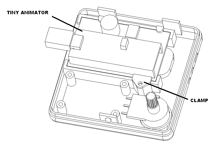
Connections to volume pot
Solder to the volume pot using the following table.
| Pot pos | Wire Color |
| Left most pin | BLK |
| Wiper | ORG |
| Right most pin | BLU |
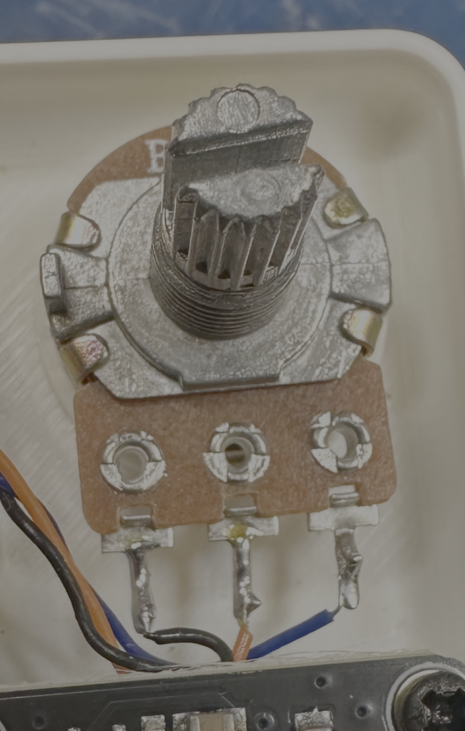
Mount preamp board
Mount the preamp board to the lower case using 4 M2.3 x 6 pan head screws as shown.
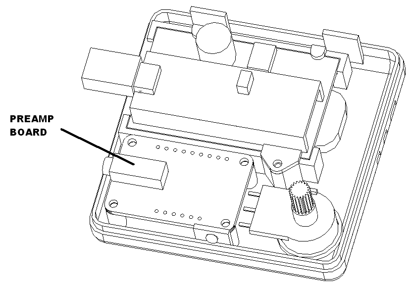
Connections to preamp board
Solder to the I2S preamp board using the following table.
| Connect to | Cable Color |
| VIN | RED |
| GND | BLK |
| MUTE | PUR |
| DIN | YEL |
| LRC/WSEL | GRN |
| BCLK | BRN |
Test the assembly
Plug in the power supply and amp. Plug in the bars and bolt shipping with the unit.
Turn everything on. The bars and bolts should go through self test and animator should announce it is on the network.
Press the left button and the lightning animation should start. Test the volume by turning the volume knob.
If every thing is good unplug everything and install the case cover and volume knob.
Packaging
Tape the mid inserts to the top and bottom of the subwoofer was shown.
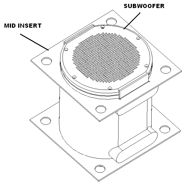
Insert presentation insert without label on the bottom of the box. Place subwoofer in box. Label the top presentation insert and put in the top of the box. Seal the box and label.
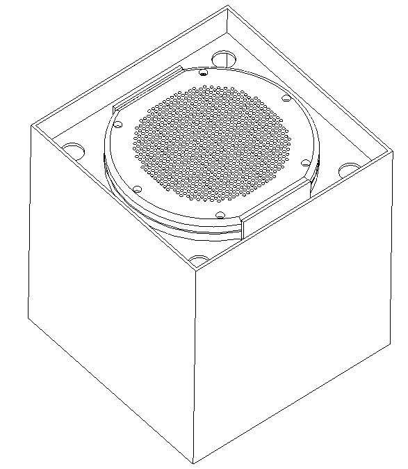
Tape two speaker to the mid insert as shown. Tape the power supply below. Tape the animator control on top as shown.
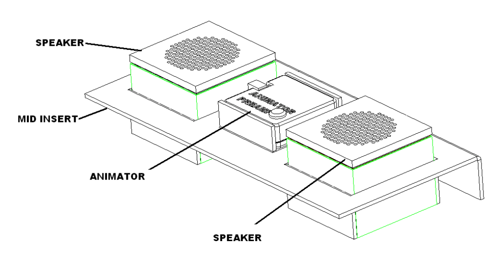
Insert this assembly in the box. Place the amp to the right, the amp power supply to the left and audio cable on top.
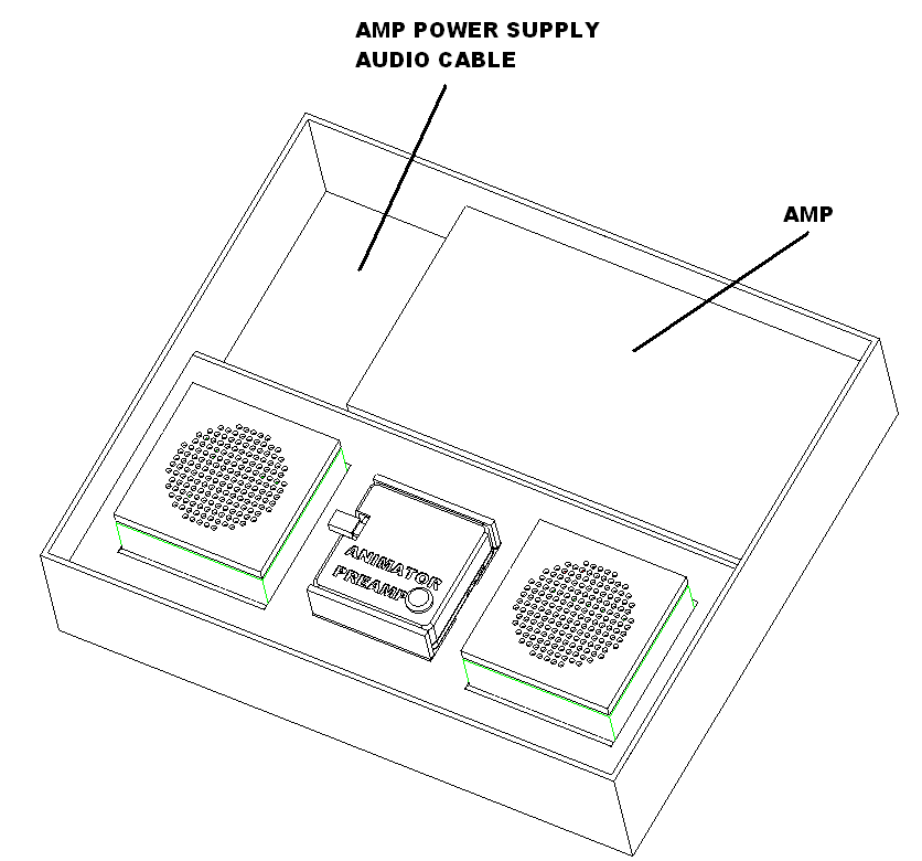
Apply label to the presentation insert and place presentation insert the the box as shown. Seal the box and apply the label.
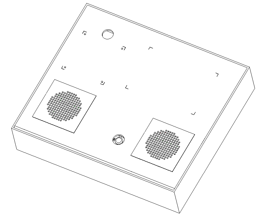
Place a three bolt, 2 two bolts and 2 one bolt in box with microfiber towels to protect them. Seal the box and apply the label.