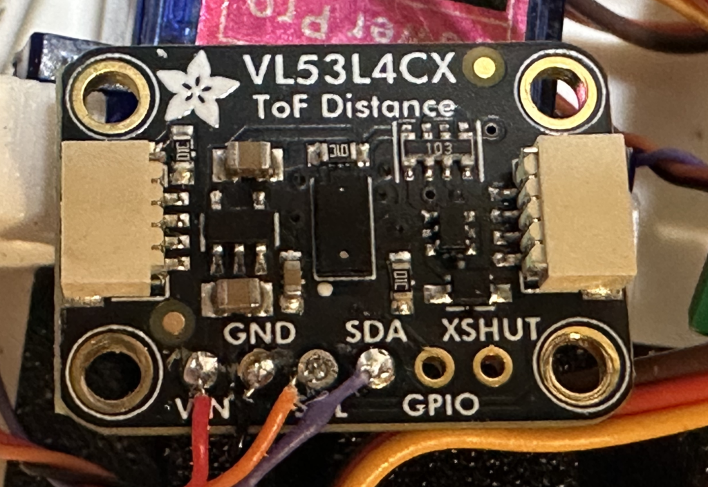
Tiny animator front side connections
The front side of the animator tiny board has connections for the left and right speaker.

Speakers
Cut two white and two gray 22 gauge wires 10 inches long. Strip and tin.
| Function | Connect to | Wire length/gauge/color/dir |
| Left speaker | LEFT SPK | 10″ / 22 / WHT+ GRY-/down |
| Right speaker | RIGHT SPK | 10″ / 22 / WHT+ GRY-/down |
Solder to the animator using the following table and label 3″ from the end “LEFT SPK” and “RIGHT SPK”.
| Connect to | Cable Color |
| GND (SQ pad 1) | GRY |
| Signal (pad 2) | WHT |
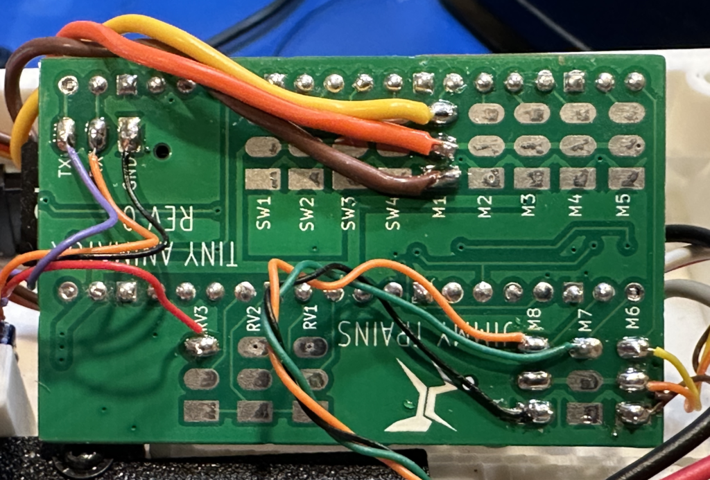
Tiny animator backside connections
The backside of the board has all the connections for the servo motors, switches, neopixels, and volume control.

Volume pot
Twist black, blue and orange 30 gauge wire together. Cut to 6″ lengths. Solder to the animator as shown
| Function | Connect to | Wire length/gauge/color/dir |
| Volume pot | RV1 | 6″ / 30 / Varies / up |
Solder to the animator using the following table.
| Connect to | Pot pos | Wire Color |
| RV1 GND (SQ pad 1) | Left most pin | BLK |
| RV1 Input (pad 2) | Wiper | BLU |
| RV1 3V+ (pad 3) | Right most pin | ORG |
Switches
Cut two brown wires 10″ long, solder and shrink wrap to left switch. Label switch wire with “LEFT SW”, 3″ from end.
Cut two blue wires 10″ long, solder and shrink wrap to right switch. Label switch wire with “RIGHT SW”, 3″ from end.
| Function | Connect to | Wire length/gauge/color/dir |
| Left switch | SW1 | 10″ / 26 / BRN / up |
| Right switch | SW2 | 10″ / 26 / BLU / up |
Solder to the animator using the following table.
| Connect to | Cable Color |
| GND (SQ pad 1) | BRN / BLU |
| Signal (pad 3) | BRN / BLU |
Back side connections continued
Use the photo below for reference.
Neopixels
This is the detail for the female neopixel cable.
| Function | Connect to | Wire length/gauge/color/dir |
| Neopixels | M6 | 6″ / 22 / Varies / up |
Solder to the animator using the following table.
| Connect to | Neo pixel Cable Color |
| M6 GND (SQ pad 1) | WHT or BRN |
| M6 5V (pad 2) | RED or ORG |
| M6 signal (pad 3) | GRN or YEL |
Servos
Cut female servo harnesses to 3″ lengths. Label female end with SERVO 1.
| Connect to | Servo cable id | Wire length/gauge/color/dir |
| M1 | Servo 2 | 3″ / 26 / Varies / down |
Solder to the animator using the following table.
| Connect to | Cable Color |
| GND (SQ pad 1) | BRN |
| 5V (pad 2) | RED |
| Signal (pad 3) | YEL |
DC motor controller
Twist orange, green, black and cut to 5″ lengths.
Solder to the animator using the following table.
| Connect to | Cable Color |
| M8 signal (pad 3) | ORG |
| M7 signal (pad 3) | GRN |
| M8 GND (pad 1 | BLK |
Distance sensor
Twist purple, orange, black and red 30 gauge wires and cut to 5″ lengths.
Solder to the animator using the following table.
| Connect to | Cable Color |
| TX | PUR |
| RX | ORG |
| RV3 3V (pad 3) | RED |
| GND | BLK |
Connections to sensor and driver boards
Motor controller
Twist orange, green, black and cut to 5″ lengths.
Solder to the motor controller using the following table.
| Connect to | Cable Color |
| IN1 | GRN |
| IN2 | ORG |
| GND | BLK |
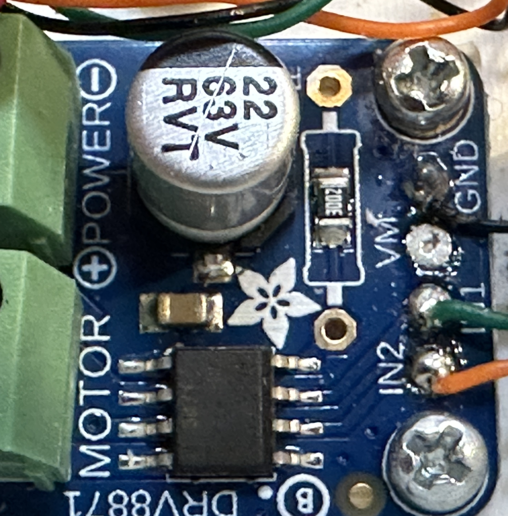
Distance sensor
Twist orange, green, black and cut to 5″ lengths.
Solder to the distance sensor using the following table.
| Connect to | Cable Color |
| SDA | PUR |
| SCL | ORG |
| VIN | RED |
| GND | BLK |