
Controller assembly
Solder pi pico W to the animator tiny board.
Install circuit python CP_pico2_w-en_US-9.2.7.uf2. Copy code onto pico.
Copy sd files to microSD card. Insert microSD card into animator tiny board.
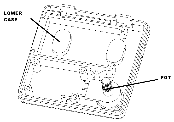
Glue the pot to the lower case as shown. Set aside to dry.
Prepare wires
Cut two brown wires 10″ long, solder and shrink wrap to left switch. Label switch wire with “S1 LEFT SW”, 5″ from end.
Cut two blue wires 10″ long, solder and shrink wrap to right switch. Label switch wire with “S2 RIGHT SW”, 5″ from end.
Cut female end of a servo extension cable to 10″ Label the connector “M1 FELLER”.
Cut female end of a servo extension cable to 10″ Label the connector “M2 TREE”.
Cut 26 gauge white and grey wire to 10″. Label the wires “SPEAKER” 5″ from end.
Cut 22 gauge two black wires to 10″. Label the wires “12-18V AC/DC” 5″ from end.
Route wires
Route the neo pixel cable in the top slot of the lower case, the right switch cable next and then the left switch cable.
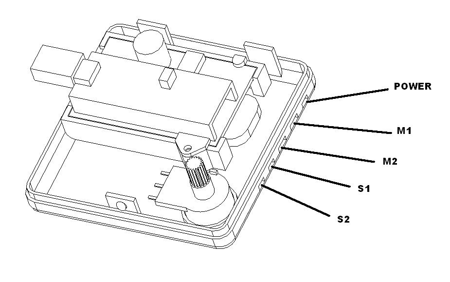
Strip and tin all wires.
Tiny animator backside connections
The backside of the board has all the connections for the switches, servos, and volume control.

Volume pot
Twist black, blue and orange 30 gauge wire together. Cut to 4″ lengths. Solder to the animator as shown
| Function | Connect to | Wire length/gauge/color/dir |
| Volume pot | RV1 | 4″ / 30 / Varies / bottom |
Solder to the animator using the following table.
| Connect to | Wire Color |
| RV1 GND (SQ pad 1) | BLK |
| RV1 Input (pad 2) | ORG |
| RV1 3V+ (pad 3) | BLU |
Servos
| Function | Connect to | Wire length/gauge/color/dir |
| Feller servo | M1 | Varies/ 22 / Varies / bottom |
| Tree servo | M2 | Varies/ 22 / Varies / bottom |
Solder the servo harness to the animator using the following table.
| Connect to | Neo pixel Cable Color |
| MX GND (SQ pad 1) | BLK |
| MX 5V (pad 2) | RED |
| MX signal (pad 3) | WHT |
Switches
| Function | Connect to | Wire length/gauge/color/dir |
| S1 Left switch | SW1 | 10″ / 26 / BRN / bottom |
| S2 Right switch | SW2 | 10″ / 26 / BLU / bottom |
Solder to the animator using the following table.
| Connect to | Cable Color |
| GND (SQ pad 1) | BRN / BLU |
| Signal (pad 3) | BRN / BLU |
Animator board mounting
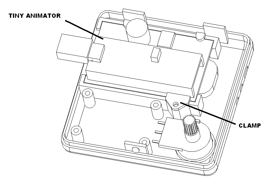
Mount the animator to the lower case using and animator clamp and one M2.3 x 6 flanged screw.
Connections to volume pot
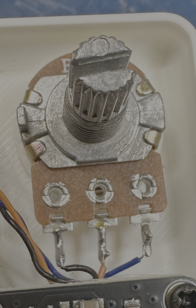
Solder to the volume pot using the following table.
| Pot pos | Wire Color |
| Left most pin | BLK |
| Wiper | ORG |
| Right most pin | BLU |
Servo platform assembly
Press feller base onto servo. Mount to the servo platform with screws provided.
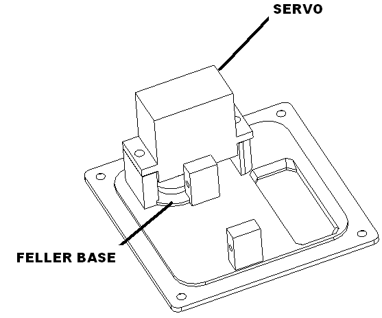
Plug in tree servo into powered up controller. Press tree base into servo as shown an fasten with screw provided.
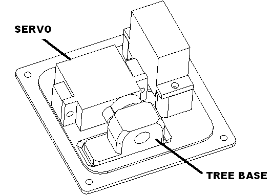
Unplug servo and rotate to attach to the feller base with the screws provided.
Packaging
Laser cut presentation insert, mid insert and bottom insert.
Insert bottom insert into box.
Attach speaker to mid insert, attach controller to mid insert. Insert this in box.
Heat seal servo mechanism in bag, heat seal figure in bag. Tape these down to mid insert.
Heat seal clump foliage in bag.
Tape sd card adapter to inside of box.
Put two tree armatures in box.
Attach inner label to presentation insert.
Seal box and put label on box.