
Pre assembly
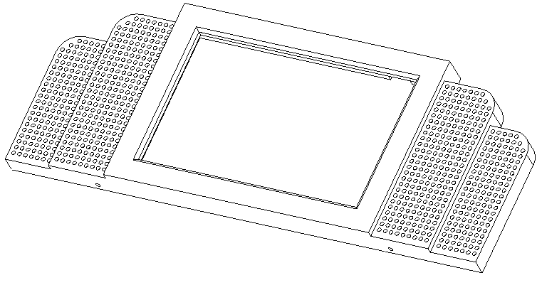
Glue speaker bezels to screen bezel as shown. Set aside to dry.
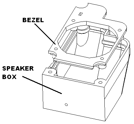
Glue speaker bezels into speaker box as shown. Set aside to dry.
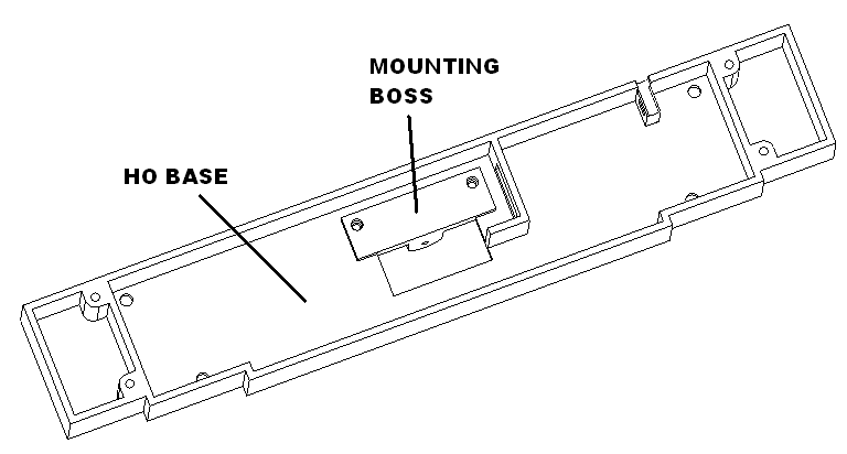
Glue mounting boss into ho base using two M2.3 x 6 screws as temporary clamps. Set aside to dry.
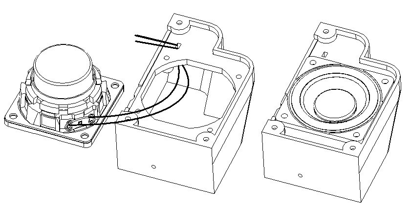
Cut white and gray 22 gauge wire to 6″ lengths. Feed through speaker wire holes. Solder to the speakers. Screw speaker in with m2.6 x 8 screws.
Twist 2 pieces of 30 gauge wire together. Cut to 5″ lengths. Put shrink wrap on wires. Solder to switches. Shrink shrink wrap.
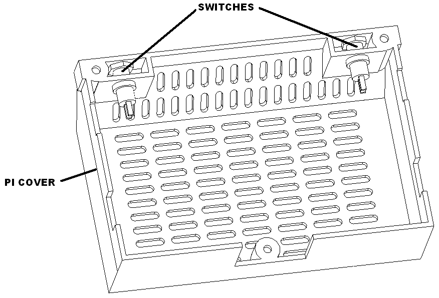
Install switches in rear cover. Rotate so the lead up up and down so they are able to clear the pi board.
Cut one 3 wire extension to 6″ on female side. Save male side for later use. Label female female side NEOPIXELS.
Cut two 3 wire extension to 6″ on female side. Label female and male side L/R SW and 3/4 SW.
Assembly
Insert brightness button into bezel as shown.
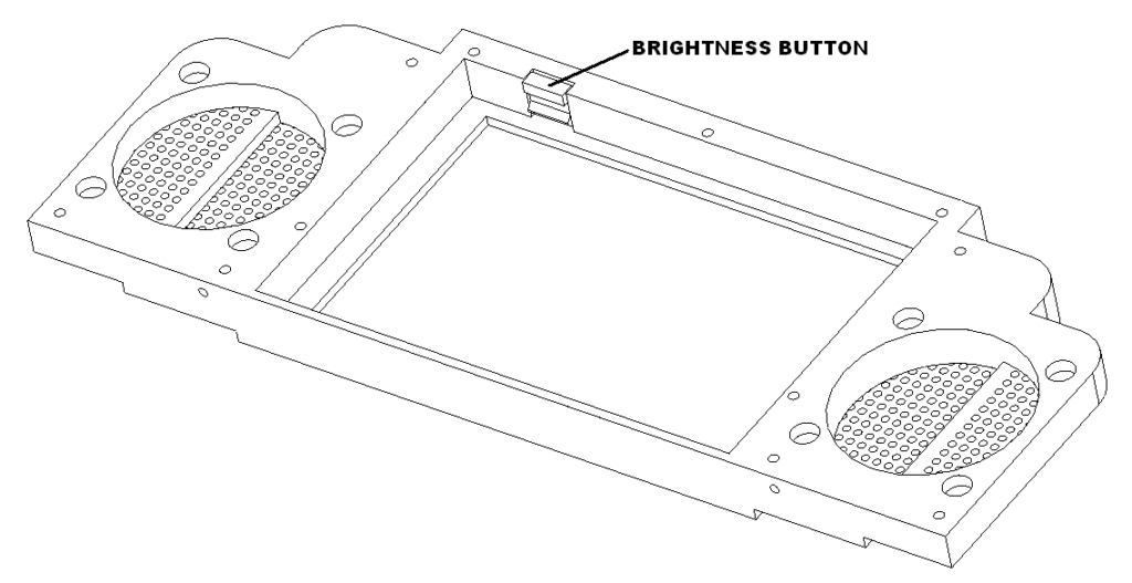
Set screen into bezel. Attach top rubber clamp first with one m2.3×8 screw. Then attach the left and right rubber clamps with two m2.3×8 screws. Screw in four hex standoff to the touchscreen.
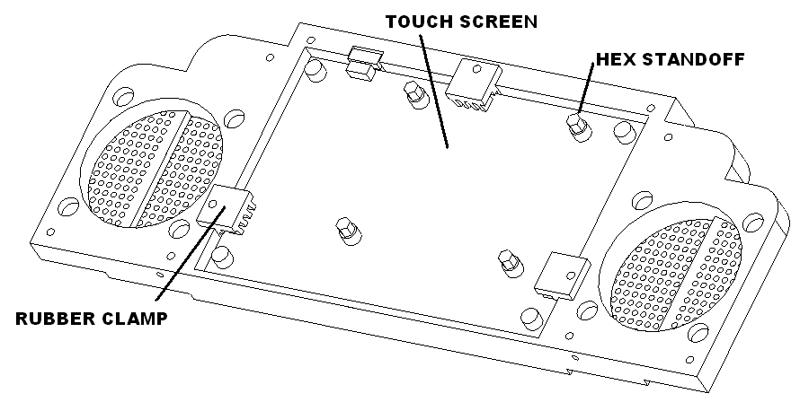
Put the pi imaged microSd card in the pi board.
Mount the pi using the screws supplied. Install the touchscreen flex cable.
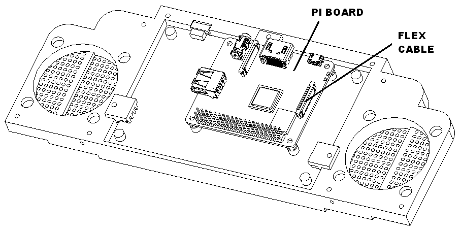
Attach the right speaker with 3 m2.3 x 8 screws. Then attach the left speaker.
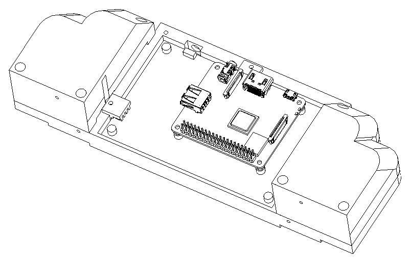
Insert the USBC power connector into the drive in bottom base.
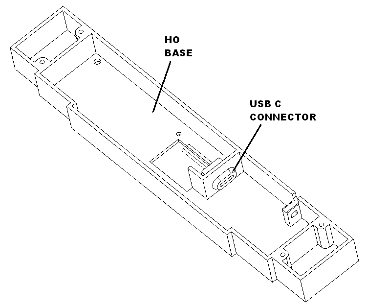
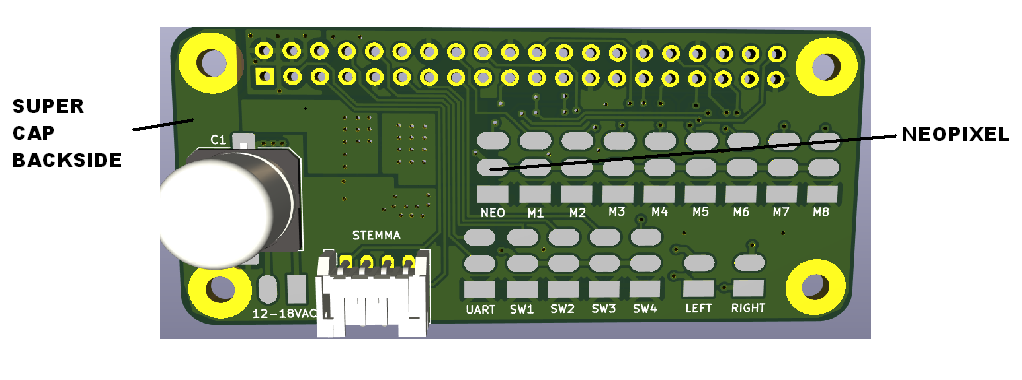
Solder usbc bulkhead connector to super cap pads on back side of the ANPISBC board. Solder the right speaker going to the left terminal and the left speaker going to the right terminal. White is positive gray is negative.
Install the drive in base to the drive in using 4 M2.3×8 screws.
Install the ANPISBC on the pi board. Install usb dongle for portable keyboard. Mark unit and the keyboard with a unique number. Since the dongle and keyboard are tied to each other.
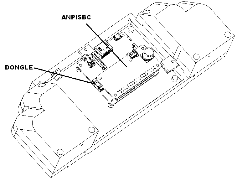
Power up the animator it should announce that is setting up. Power down if the speakers are working.
Solder female NEOPIXELS harness, facing right, to NEO pads. White to ground, red to pin 2 and green to pin 3.
Solder the female SW 3/4 harness, facing right, to SW3, and SW4 as follows. White to SW3 pin 3, and red to SW4 pin 3. Solder the remaining black wire to SW3 ground.
Solder the female SW L/R harness, to S1 and S2 as follows. First strip all wires for the switch at least 1/4 long. Then wrap the white wire with one of the wires for the left switch and tin. Repeat with the red wire for the right switch. Combine the remaining wires from the switches and wrap the black wire and tin.
Then cut all wires tinned ends to about 1/8 inch and solder white wire to S1 pin 3, red wire to s2 pin 3, and black wire to s1 ground.
Plug in the pi it should boot and display Jimmy Trains logo. Verify the keyboard is working.
Press the left button and an animation shall play. Press the right button to pause.
Plug in the 4 button remote and confirm all the buttons work.
Clean the screen before packing.
Packaging
The mid insert packing assembly consist of the following parts. Tape the drive in u shape corners as shown. Insert in holes in mid insert and tape tabs. Bend power supply u shape and insert in mid insert holes and tape.

Place the power supply as shown.
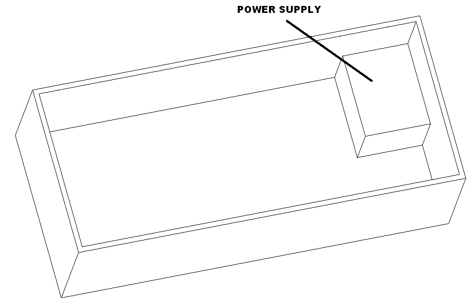
Insert the mid insert into box as shown.
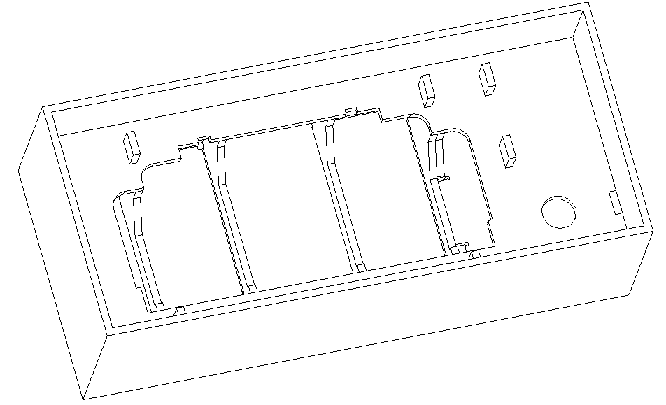
Place the drive in and power supply as shown.
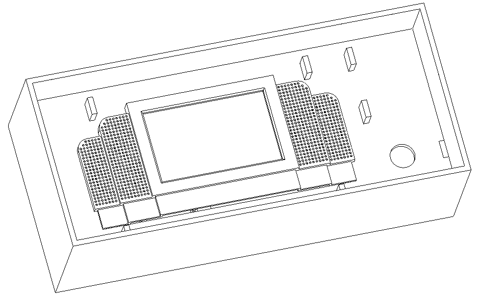
Place drive-into the box. Bag the four button switch and tape down to the mid insert in the upper right corner.
Bend tabs up in presentation insert as shown. Insert keyboard and tape. Insert foam and tape.
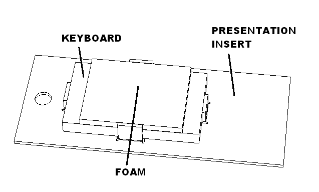
Flip and place in box as shown and apply a inner label on the right. Put cutting template on top.
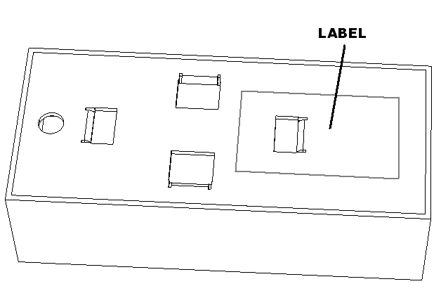
Close box and apply product label.