
Preassembly
Glue speaker grills to screen bezel as shown. Set aside to dry.
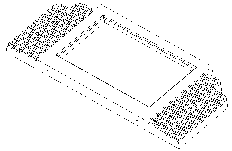
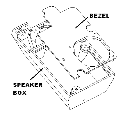
Glue the bezel into the speaker box. Set aside to dry.
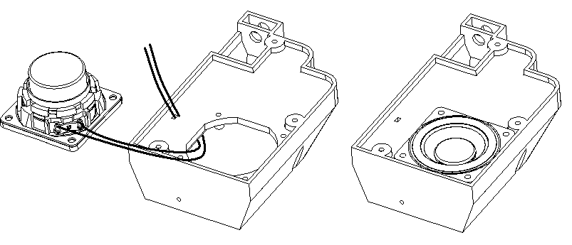
Cut white and gray 22 gauge wire to 9″ lengths. Solder to the speakers. Screw speaker in with m2.6 x 8 screws.
Install switches in speakers.
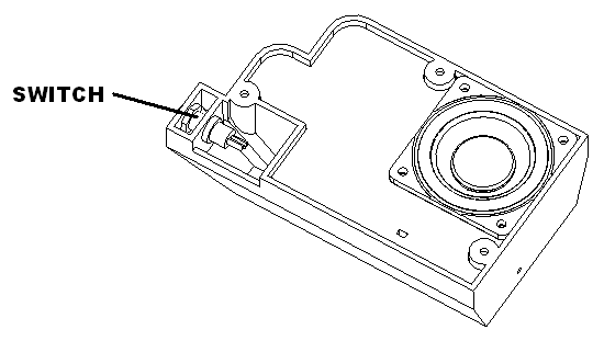
Twist 2 pieces of 30 gauge wire together. Cut to 6″ lengths. Solder to switches in speakers. Set aside.
Cut usb power supply to screen to 10 inches. Carefully strip and just leave black and red wires strip and tin.
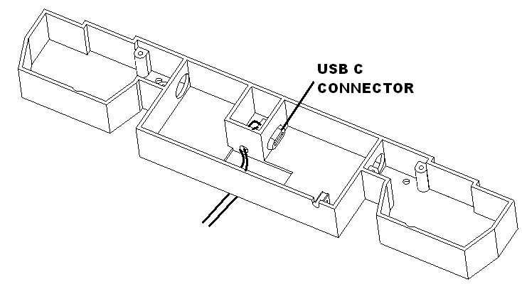
Insert USB C power connector into drive-in base.
Assembly
Bend the hdmi cable to the left going to the center of the assembly. Bend the usb cable to the right going to the center of the assembly
Plug in cable and set screen into bezel. Attach top thick rubber clamp first with one m2.3×8 screw. Then attach the left and right rubber clamps with two m2.3×8 screws.
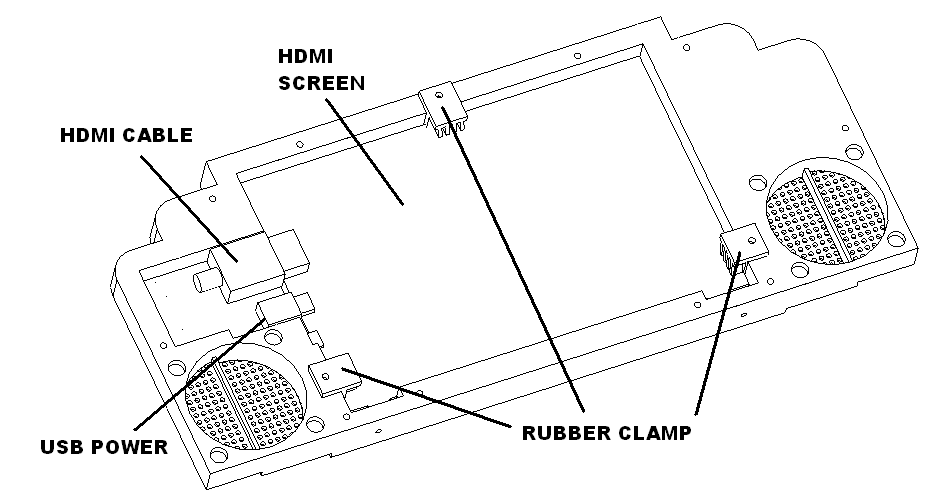
To hold the hdmi cable and usb cable down attach the right speaker with 3 m2.3 x 8 screws. Then attach the left speaker.
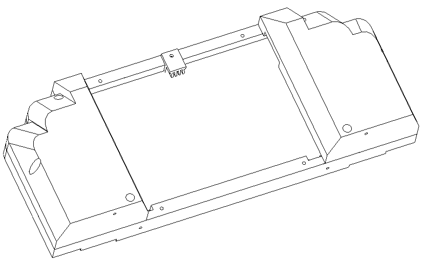
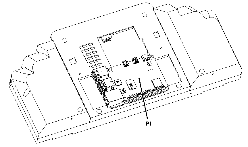
Route all the wires and cables through the large hole in the pi mount cover. Install the pi mount using 4 2.3×8 screws. Tape the speaker and switch wires so they don’t interfere with mounting the pi.
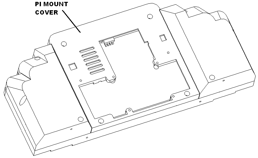
Put the pi imaged microSd card in the pi board. Bend the hdmi cable to connect properly to the pi board with out any strain. Mount the pi to the pi mount cover with 4 M2.3X6 screws.
Install usb dongle for portable keyboard. Mark unit and the keyboard with a unique number. Since the dongle and keyboard are tied to each other.
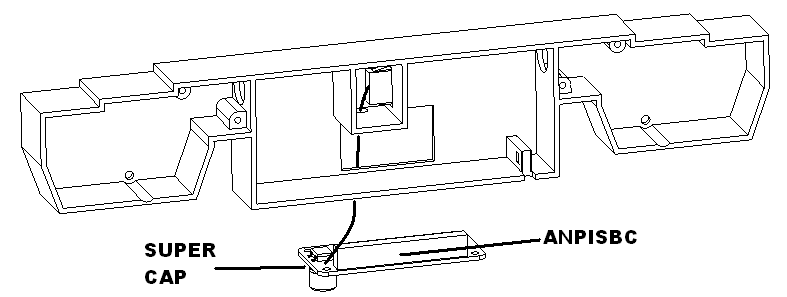
Solder USB C power cable to the ANPISBC board to the super cap pads.
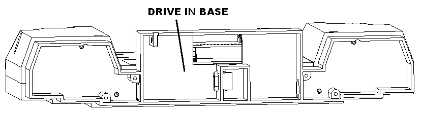
Mount the base to the drivein using four M2.3 x 8 screws.
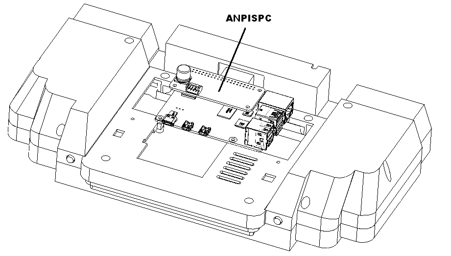
Plug in the ANPISBC board into the pi as shown.
Apply solder to m8 positive and negative terminal. Solder the usb cable to those pads.
Power up the animator it should announce that is setting up. Power down if the speakers are working.
Solder, neo pixels harness, to neo pads. Solder the switch harness to S1, S2, S3, S4. White for the left switch, and red for the right switch. White for 3, and red for 4. Tie the left switch wires to the left to white and right to red. Combine the remaining wires for ground which is attached to sw1 ground. sw3 ground is used for the 3/4 harness.
Plug in the pi it should boot and display Jimmy Trains logo. Verify the keyboard is working.
Press the left button and an animation shall play. Press the right button to pause.
Plug in the 4 button remote and confirm all the buttons work.
Clean the screen and put into the packaging.