
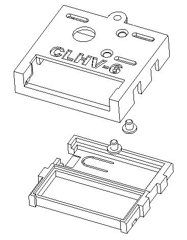
Print out the case parts using white FR rated ABS.
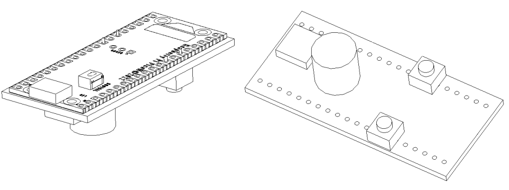
Solder pi pico w to the 5 volt animator board. Solder two switches on the top as shown at GND/P20 and GND/P11. Clip the leads on the backside.
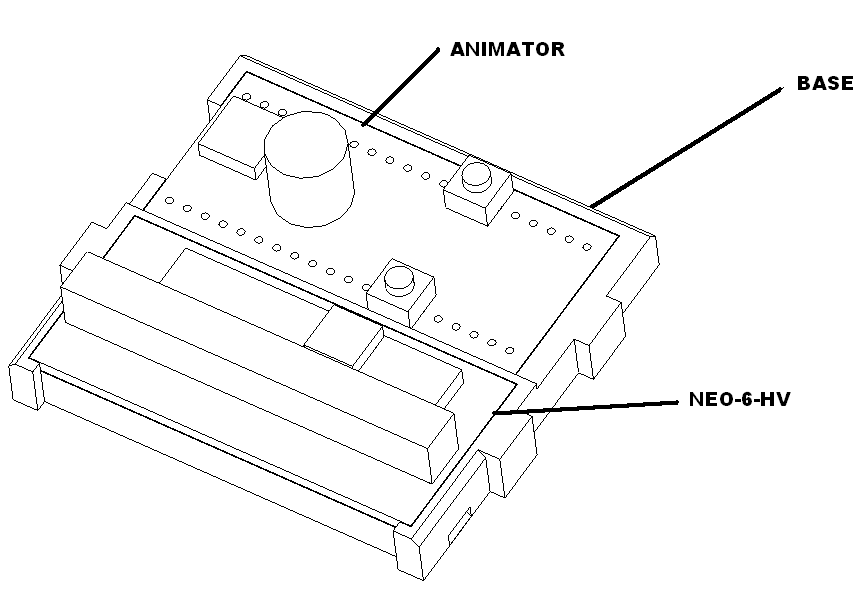
Place the animator board and the neo-6-hv board into the assembly as shown.
Cut black, blue, yellow 30 gauge wire to xxx inches and twist.
And solder black, blue and yellow 30 gauge wire to the neopixel using the following table.
| Connect to | Wire Color |
| GND | BLK |
| Input | YEL |
| 5V | BLU |
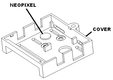
Glue neopixel indicator to case top and set aside to dry.
Board connections
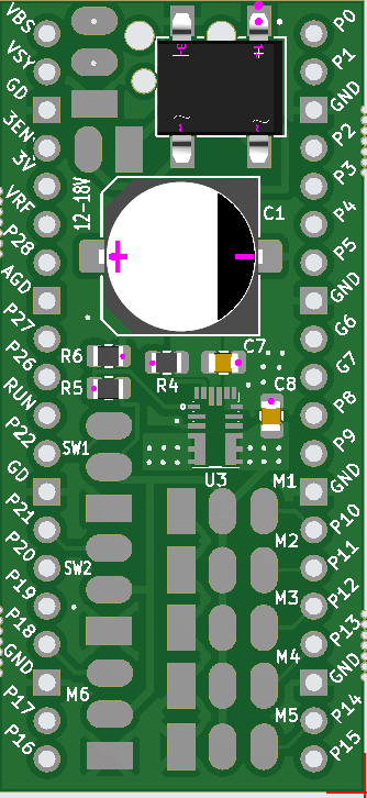
Connect the male power cable to the 12-18V PWR inputs on the animator board using the following table.
| Connect to | Wire Color |
| PWR (sq pin 1) | BLK |
| PWR (pin 2) | RED |
Cut 22 gauge neopixel cable to xxx inches. Connect the neo-6-hv to the animator board using the following table:
| Connect to | Wire Color |
| M3 GND (sq pin 1) | WHT |
| M3 5V (pin 2) | RED |
| M3 Output (pin 3) | GRN |
Connect the output of the neo-6-hv to a female neopixel cable using the following table:
| Connect to | Wire Color |
| GND | WHT |
| Output | GRN |
| 5V | RED |
Connect the indicator neo pixel to the animator board using the following table:
| Connect to | Wire Color |
| M4 GND (sq pin 1) | BLK |
| M4 5V (pin 3) | BLU |
| M4 Output (pin 3) | BLU |
Glue the wires down with liquid CA glue and spray on accelerator. Let dry.
Tap buttons to lid and snap lid on.
Load latest software on device.