Tiny animator front side connections
The front side of the animator tiny board has connections for the left and right speaker.

Speakers
Cut two white and two gray 22 gauge wires 10 inches long. Strip and tin.
| Function | Connect to | Wire length/gauge/color/dir |
| Left speaker | LEFT SPK | 10″ / 22 / WHT+ GRY-/down |
| Right speaker | RIGHT SPK | 10″ / 22 / WHT+ GRY-/down |
Solder to the animator using the following table and label 3″ from the end “LEFT SPK” and “RIGHT SPK”.
| Connect to | Cable Color |
| GND (SQ pad 1) | GRY |
| Signal (pad 2) | WHT |
Tiny animator backside connections
The backside of the board has all the connections for the servo motors, switches, neopixels, and volume control.

Volume pot
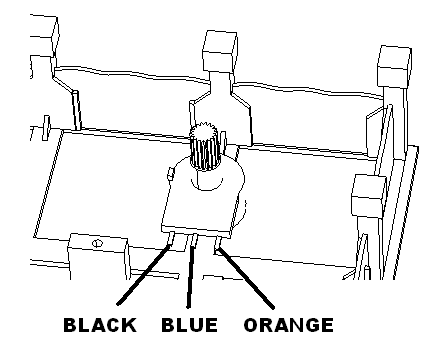
Twist black, blue and orange 30 gauge wire together. Cut to 6″ lengths. Solder to the animator as shown
| Function | Connect to | Wire length/gauge/color/dir |
| Volume pot | RV1 | 6″ / 30 / Varies / up |
Solder to the animator using the following table.
| Connect to | Pot pos | Wire Color |
| RV1 GND (SQ pad 1) | Left most pin | BLK |
| RV1 Input (pad 2) | Wiper | BLU |
| RV1 3V+ (pad 3) | Right most pin | ORG |
Neopixels
This is the detail for the female neopixel cable.
| Function | Connect to | Wire length/gauge/color/dir |
| Neopixels | M8 | 6″ / 22 / Varies / up |
Solder to the animator using the following table.
| Connect to | Neo pixel Cable Color |
| M8 GND (SQ pad 1) | WHT |
| M8 5V (pad 2) | RED |
| M8 signal (pad 3) | GRN |
Switches
Cut two brown wires 10″ long, solder and shrink wrap to left switch. Label switch wire with “LEFT SW”, 3″ from end.
Cut two blue wires 10″ long, solder and shrink wrap to right switch. Label switch wire with “RIGHT SW”, 3″ from end.
| Function | Connect to | Wire length/gauge/color/dir |
| Left switch | SW1 | 10″ / 26 / BRN / up |
| Right switch | SW2 | 10″ / 26 / BLU / up |
Solder to the animator using the following table.
| Connect to | Cable Color |
| GND (SQ pad 1) | BRN / BLU |
| Signal (pad 3) | BRN / BLU |
Servos
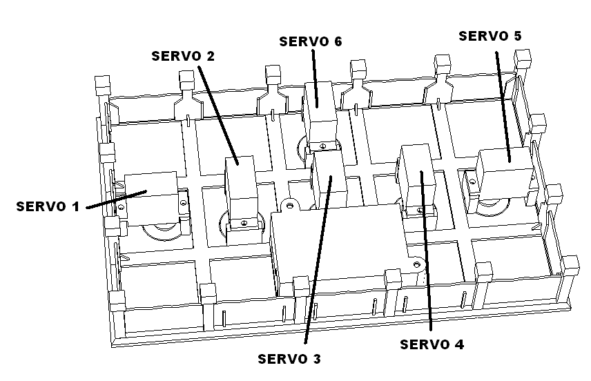
Cut female servo harnesses to 3″ lengths. Label female ends with SERVO 1, 2 and so on.
| Connect to | Servo cable id | Wire length/gauge/color/dir |
| SW4 | Servo 1 | 3″ / 26 / Varies / down |
| M1 | Servo 2 | 3″ / 26 / Varies / down |
| M2 | Servo 3 | 3″ / 26 / Varies / down |
| M3 | Servo 4 | 3″ / 26 / Varies / down |
| M4 | Servo 5 | 3″ / 26 / Varies / down |
| M5 | Servo 6 | 3″ / 26 / Varies / down |
Solder to the animator using the following table.
| Connect to | Cable Color |
| GND (SQ pad 1) | BRN |
| 5V (pad 2) | RED |
| Signal (pad 3) | YEL |
Pre assembly
Servos
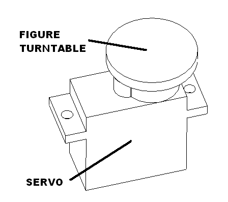
Press figure turntable onto the servo as shown. Repeat six times.
Speaker box
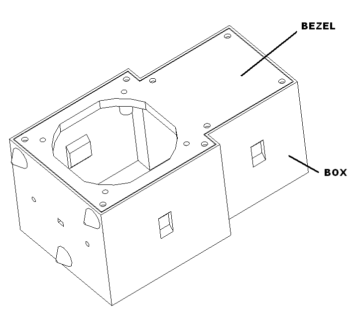
Glue the bezel in the speaker box. Repeat on more time. Set aside to dry
Spot lights
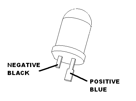
Cut LED leads. Short lead is negative cut below tab point. Long one is positive cut above tab point.
Twist black and blue 30 gauge wires together. Cut to 6″ lengths. Strip the wire back about a 1/4 of and inch. Long enough so you can wrap the wire around the lead before soldering. Solder black one to the short lead and blue one the the long lead.
Put small piece of painters tab on LED cylinder. Insert in the spot light tube as shown.
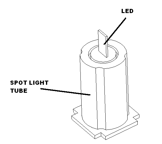
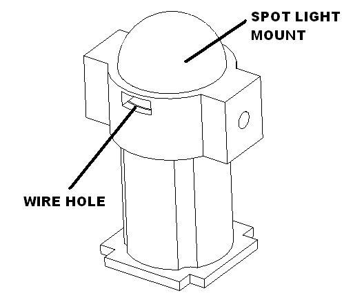
Route wires through the hole in the spot light mount and place onto the spot light tube as shown and set aside.
Stage
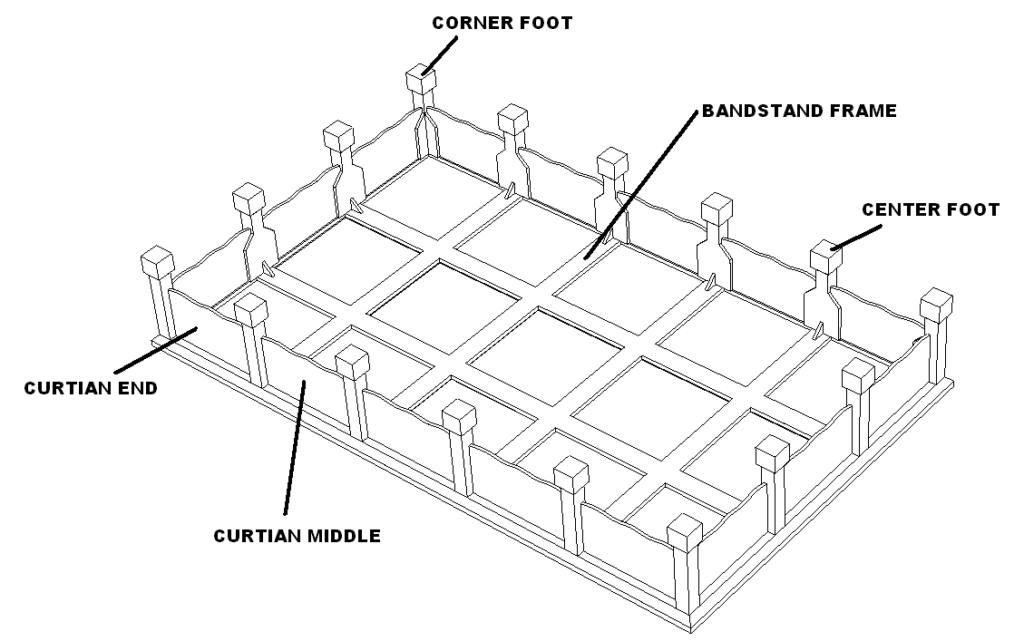
Install four corner feet, install twelve center feet as shown with glue. Attach eight end curtains with glue. Attach eight middle curtains with glue. Set aside to dry.
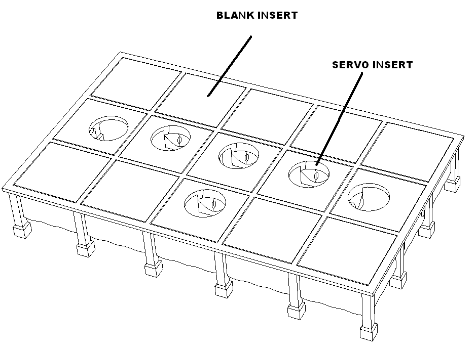
Glue in nine blank inserts and six servo inserts as shown. Set aside to dry.
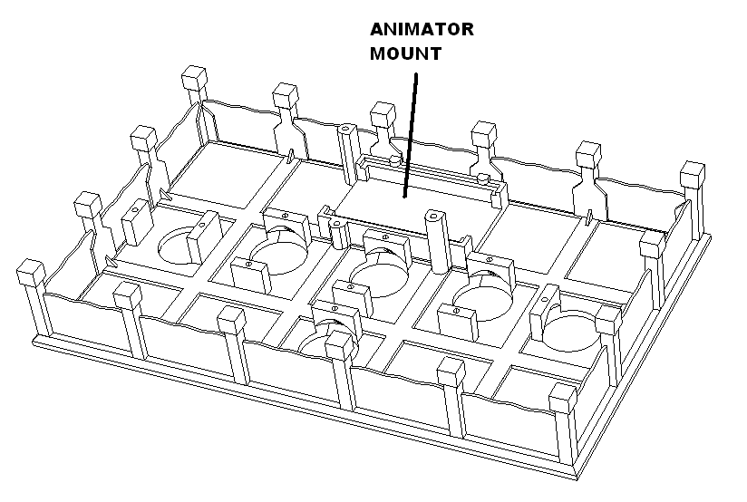
Glue in animator mount as shown.
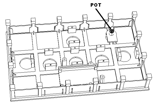
Glue pot in as shown. Set aside to dry.
Assembly
Stage
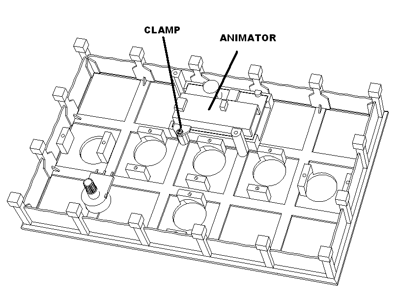
Install animator as shown using one animator clamp and M2.3 X 6 screw.
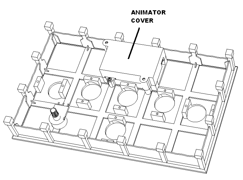
Install animator cover with two M2.3 X 6 screws.
Solder wires from animator controller to pot as shown. Black, Blue and Orange.
Screw in six servos as shown using screws provided with servos. Then plug them into the animator harness in the order shown.
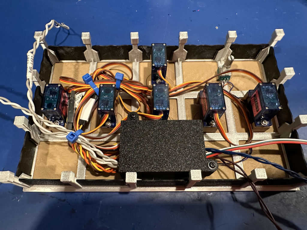
Gather all the harness wires together and zip tie them as shown.
Speaker
Cut two white and two gray 22 gauge wires 10 inches long. Insert into the speaker box from the bottom. Route wires out of the speaker hole and solder to the speakers.
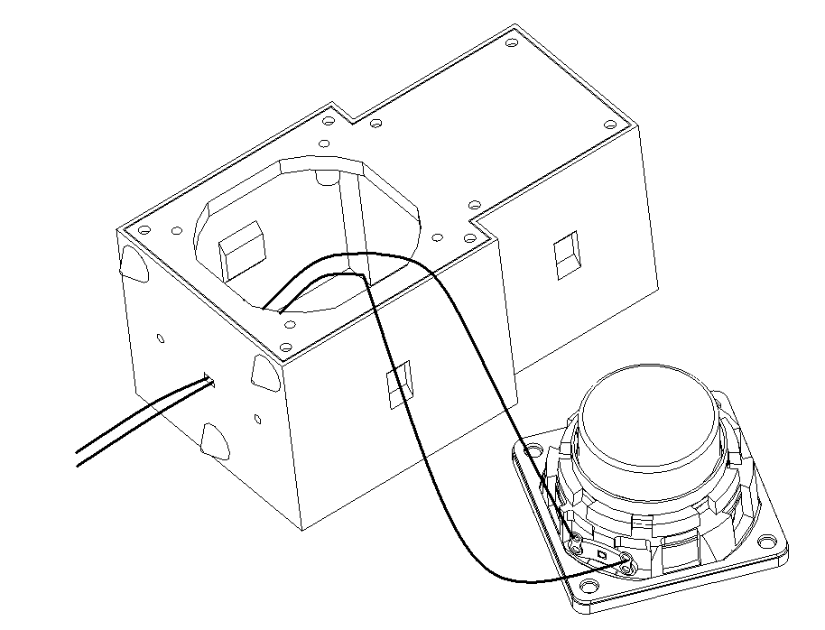
| Connect to | Cable Color |
| GND | GRY |
| Signal | WHT |
Install the speaker into the box using four M2.6 X 8 screws.
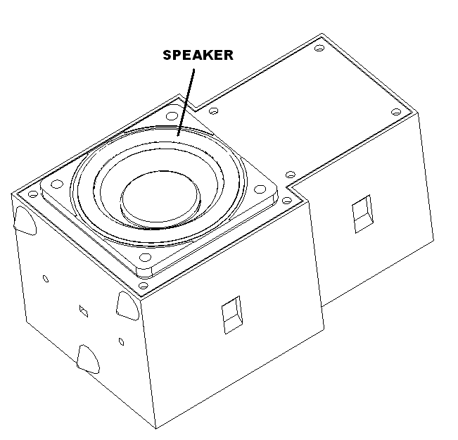
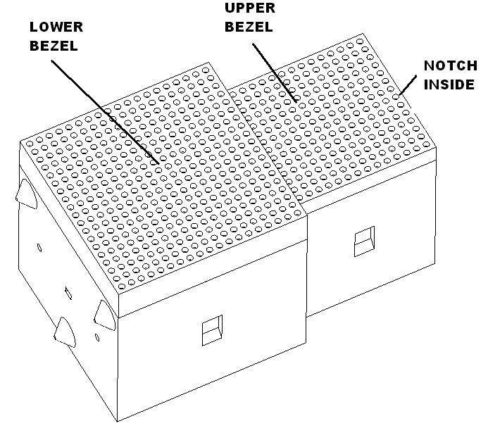
Install upper and lower bezel with a small dab of glue. Set aside to dry. Note the top bezel has a orientation notch inside that goes toward the top. Set aside to dry.
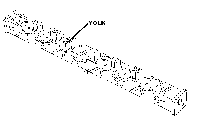
Spot light scaffold
Attach spot light yokes with M2.3 x 6 screws.
Set the control box base onto the front scaffold as shown. Do not attach yet.
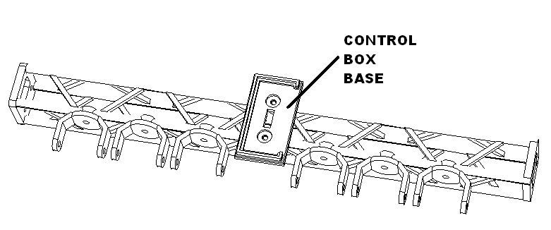
Spot light connections
Twist black, blue, purple 30 gauge wires together and cut to 18″ long lengths.
Route this cable through the left side of the scaffold and trough the center truss as shown. Then through the slot in the control box.
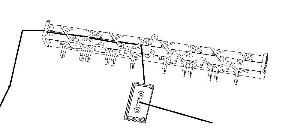
Solder to the board using the following table.
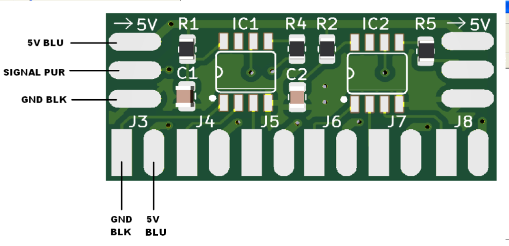
| Function | Connect to | Twisted Cable Color |
| +5V | 5V (top pad) | BLU |
| Signal | Signal (middle pad) | PUR |
| GND | GND (bottom pad) | BLK |
Route the wires of each spotlight through the bottom of the scaffold and then through the control box as shown.
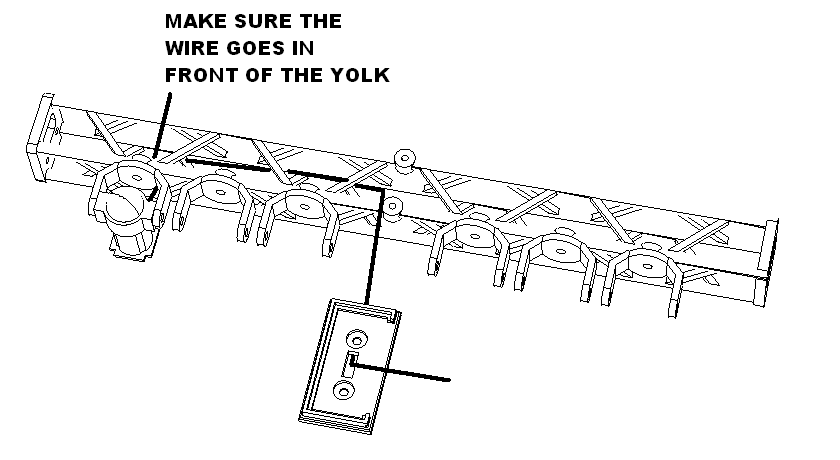
Solder to the table as below. Spot 1 and 6 are full length, then spot 2 and 5 are one spacing less and spot 3 and 4 are two spacings less. Note: spacing is the mounting pitch of each light on the scaffold.
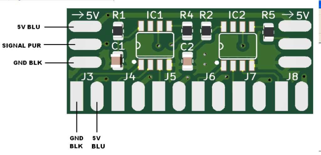
| Function | Connect to | Twisted Cable Color |
| SPOT 1 | J3 | BLK / BLU |
| SPOT 2 | J4 | BLK / BLU |
| SPOT 3 | J5 | BLK / BLU |
| SPOT 4 | J6 | BLK / BLU |
| SPOT 5 | J7 | BLK / BLU |
| SPOT 6 | J8 | BLK / BLU |
Attach all six of the spot lights to the yolks using 6 M2.3X6 screws. Attach the control box base to the front scaffold using 2 M2.3X6 screws.
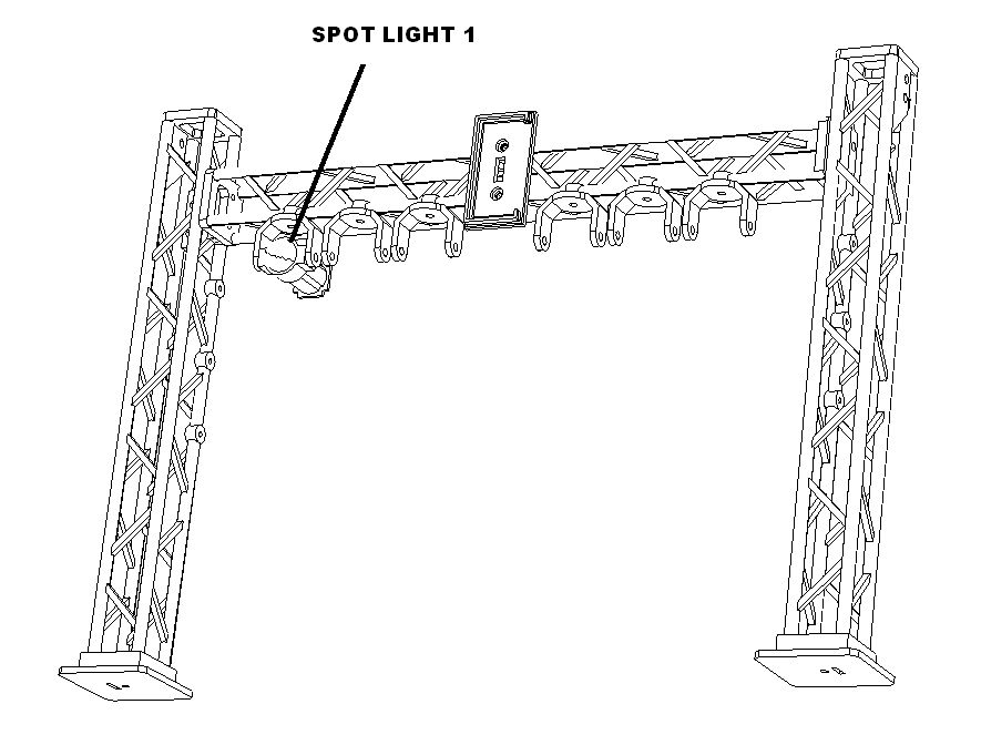
Snap the cover on.
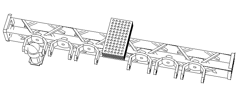
Assemble the left upright to the front scaffold while routing the supply cable through the scaffold as shown. Do not pull cable through bottom hole yet. Loosely fasten with 2 M2.3X6 screws.
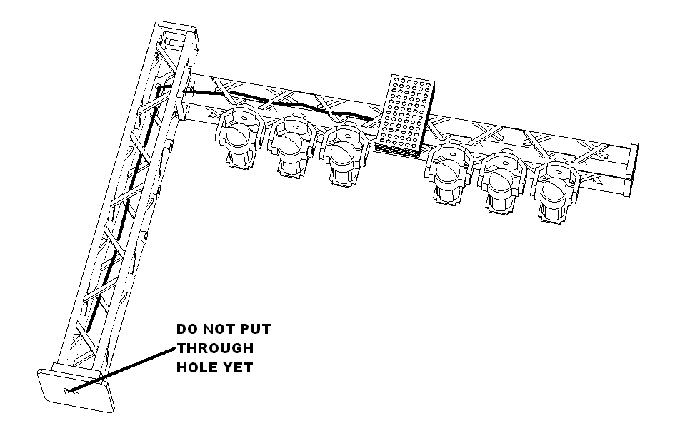
Repeat with the right upright using 4 M2.3 X 6 screws. Tighten all screws making sure the assembly is square.
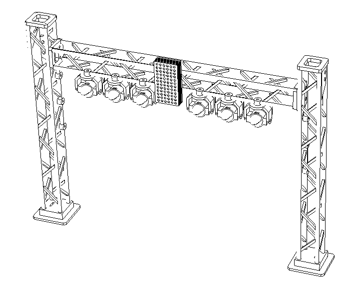
Spot light supply cable
Route the twisted supply cable through the bottom of the scaffold assembly as shown.
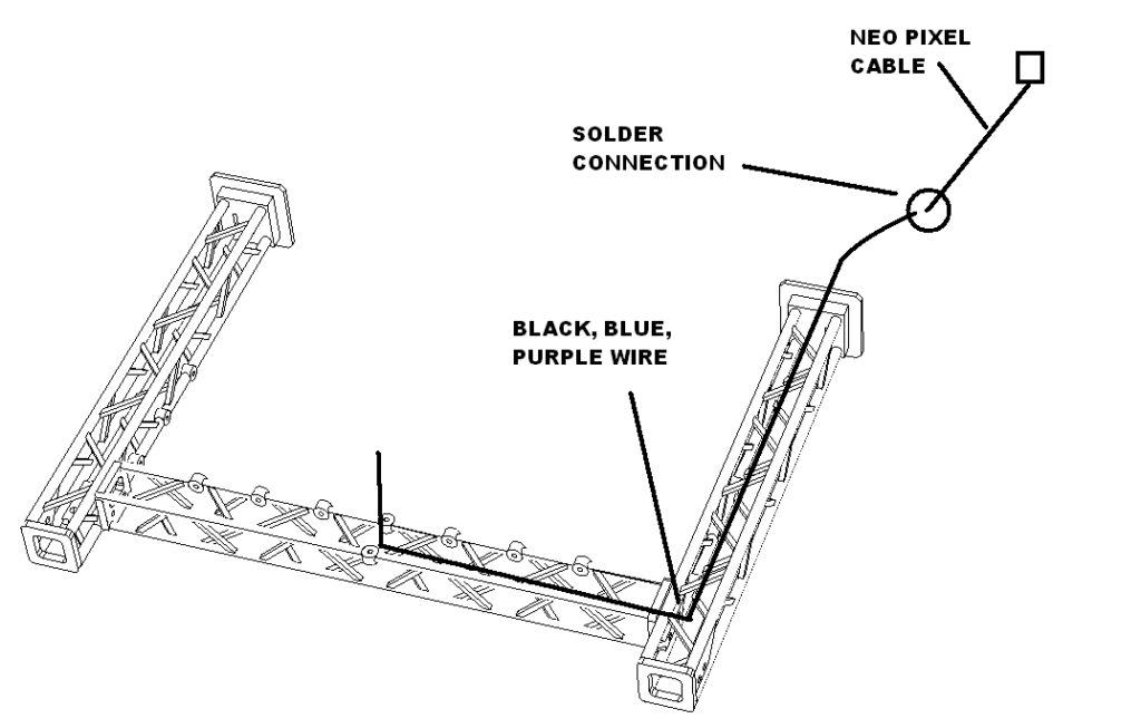
Solder and shrink wrap to a male neo pixel cable using the table below.
| Twisted 30 gauge wires | Male Neo pixel Cable |
| GND Black | WHT |
| 5V+ Blue | RED |
| Signal Purple | GRN |
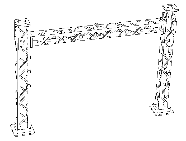
Assemble the rear scaffold using a left and right upright and 4 M2.3 X 6 screws. Make sure it is square before tightening.
Packaging
Glue two layers of inserts around holes for scaffold feet, two layers of inserts around stairs and two layers of rectangular pieces as shown. Let dry.
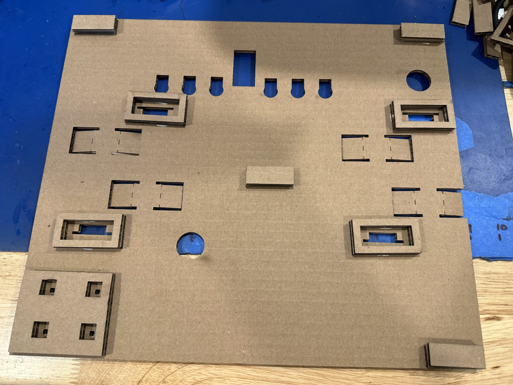
Glue one layer of stairs insert to mid insert as shown. Let dry.
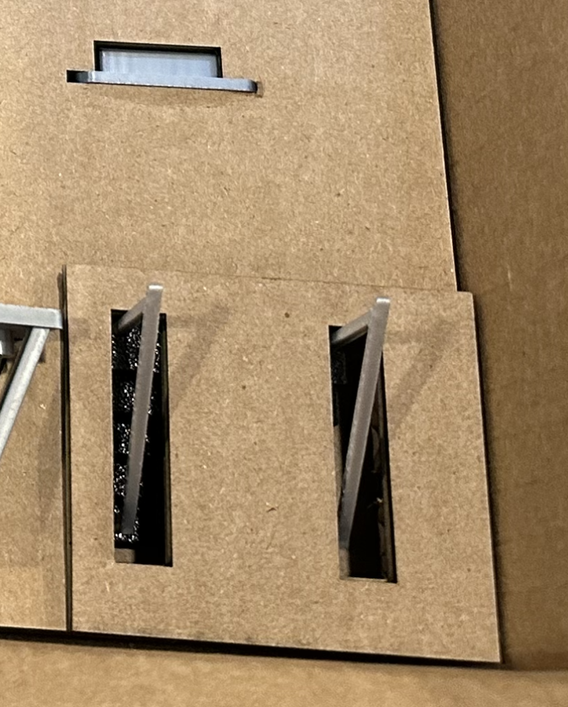
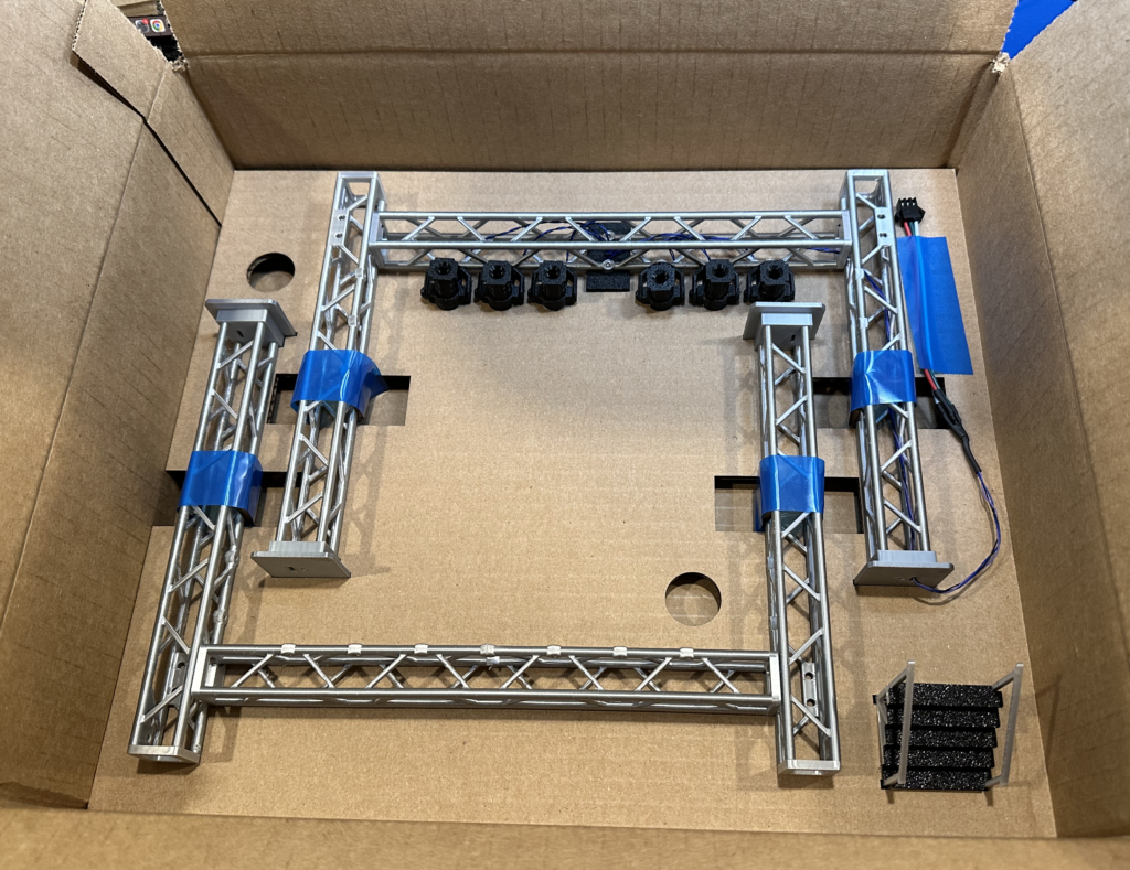
Attach spot light scaffold to lower insert as shown with blue tape. Attach rear scaffold as shown with blue tape. Tape down the wire. Place in main carton and insert stairs as shown.
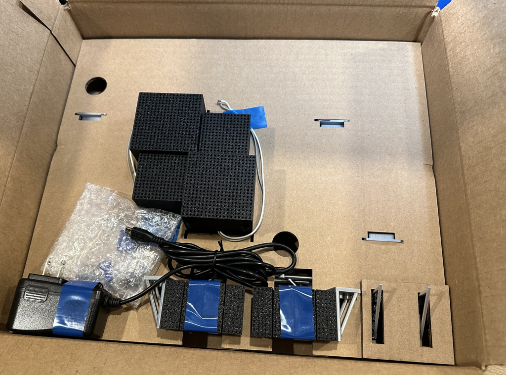
Attach speakers as shown. Attach power supply as shown. Attach line array as shown.
In a small zip lock place 14 M2.3 x 8 screws in bag. Then put this bag into a bubble bag with 4 wire nuts. Seal and place as shown.
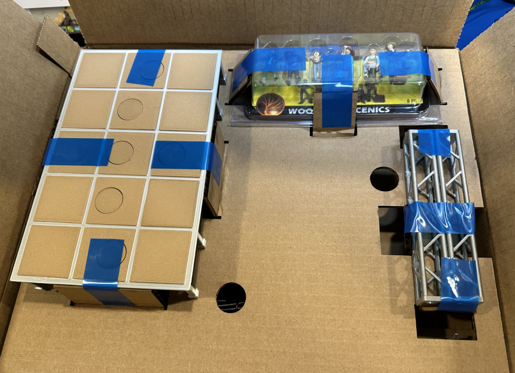
Wrap speaker wires in a loop. Loop switches around each other. Put this and the neopixel cable in a bubble bag and seal. Attach stage as shown. Cut down jug band box and tape shut. Attach jug band as shown. Attach front to back scaffolds as shown.
Turn the top layer over and put in place then attach label as shown. Table sd adapter to cardboard as shown.
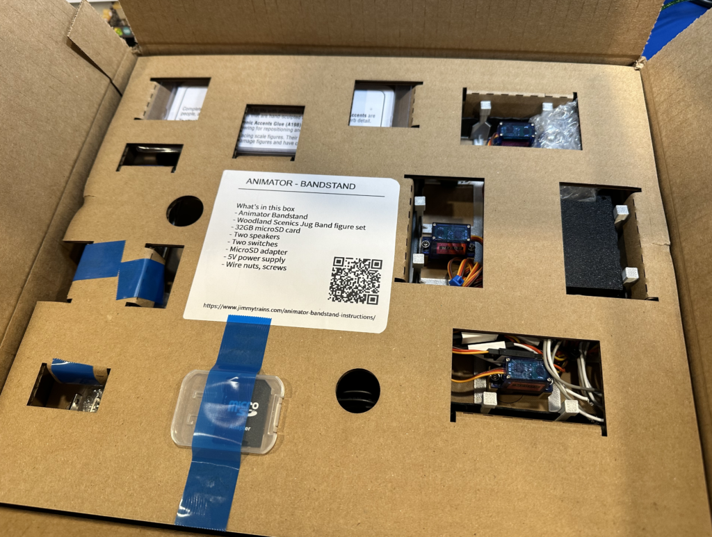
Seal box and attach product label as shown.