
Preassembly
There is a left hand and right hand version of the smart bumper. The left hand one is shown.
Turn the cover over and glue one neopixel to the cover as shown. Set aside to dry.

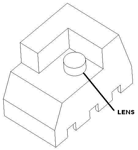
Glue lens into cover.
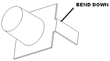
Bend spring terminals as show solder a red and black wire to them.
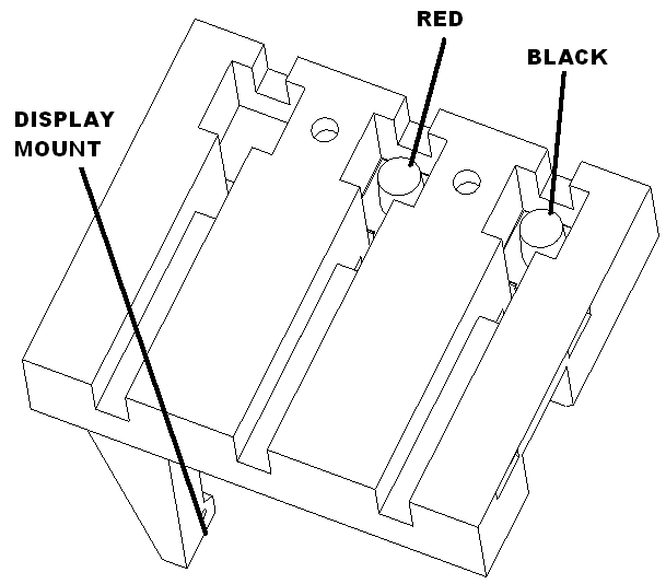
Glue into the bottom of the smart bumper in the slots that are opposite the display mounts.
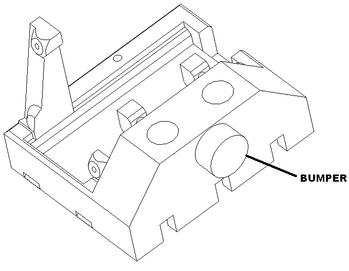
Glue rubber bumper into smart bumper.
Pico assembly
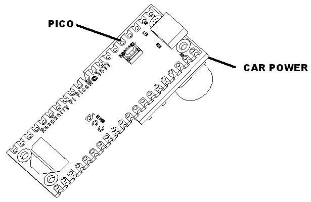
Solder the car power board to a pico 2w as shown.
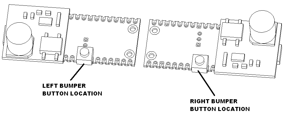
The bumper is either left facing or right. Solder the switch button as shown for each version.
Board connections
Laser distance center
Cut black, red, yellow and purple wires to 10″. Solder to the board according to the following table. Feed through the top hole in controller case.
| Pico Connection | Laser sensor | Wire Color |
| 3V+ (pico pin 36) | VIN | RED |
| GND (pico pin 3) | GND | BLK |
| SDA (pico pin 4) | SDA | PUR |
| SCL (pico pin 5) | SCL | YEL |
Neopixel indicator
Cut three 30 gauge wires to 4 inches and twist. Solder this cable to the board and to the neopixel using the following table.
| Connect from board | Connect to neopixel | Wire Color |
| GND (sup cap square pad 1) | GND (pad 3) | BLK |
| 5V (sup cap pad 2) | 5V (5V pad 1) | YEL |
| GP22 Signal (pin 29) | Signal (pad 2) | RED |
Display connections
Cut 30 gauge red, blk, blu, grn wire to 4″ and twist. Solder to the display as follows.
| Connect from board | Wire Color |
| GND (pin 1) | BLK |
| VCC (pin 2) | RED |
| SCL (pin 3) | GRN |
| SDA (pin 4) | BLU |
Display pico connections
Solder to the board as follows.
| Connect from board | Wire Color |
| VSYS (pin 39) | RED |
| GND (pin 28) | BLK |
| SDA (pin 1) | BLU |
| SCL (pin 2) | GRN |
Track power connnections
Attach two connections to the input of the diode rectifier.
| Connect from board | Wire Color |
| Left leg | BLK |
| Right leg | RED |