
Animator motor board assembly
Animator motor Rev 0 modifications
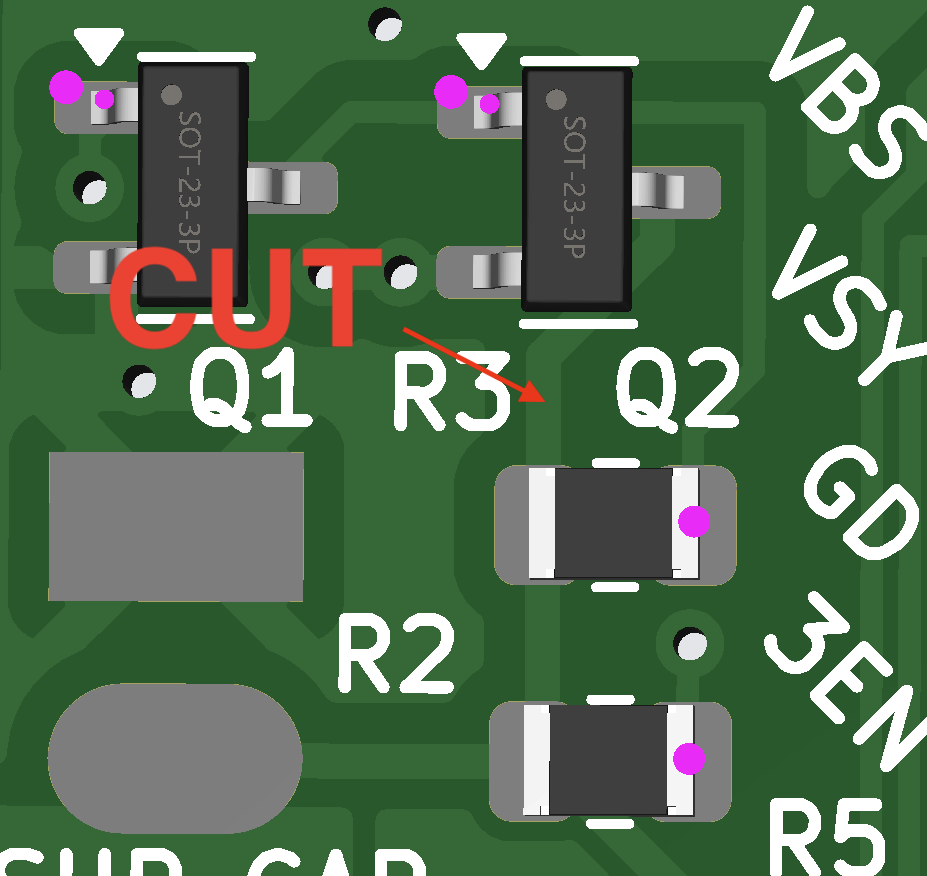
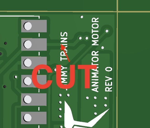
The first batch of the animator motor board has the output mosfet needing two pins swapped. To do this cut the two traces shown. One on the front side.
And one on the back side.
Then once that is done solder wires as shown.
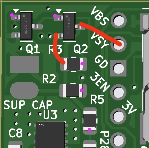
The MOSFET won’t conduct unless there is a load on VSYS. Put a 10K resistor from ground to VSYS. And hook up to train transformer. Make sure 5 volt is on VSYS.
Mount pico 2w.
Solder the pico 2w onto the castelated pads on the opposite side of the board. Make sure the usb port faces the same direction as the sd card holder.
Test the board assembly
Install the latest code on the sd card and the pico. Solder speakers to the speaker outputs. Power up the transformer. The board shall announce animations are active. Set board aside as tested.
Preassembly
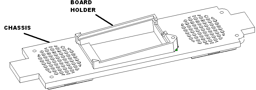
Chassis
Glue board holder into chassis set aside to dry.
Left bracket
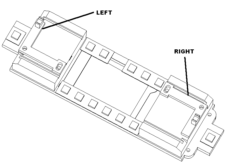
Glue the sensor to the left bracket. Hold down with screwdriver and spray accelerator on to dry quickly.
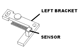
Twist orange, black and blue 30 gauge wires together and cut to 7″ lengths.
Solder the left sensor according to the following table
| Connect to | Wire Color |
| Left most pin | ORG |
| Center pin | BLK |
| Right most pin | BLUE |
Once soldered tie down wire with a dab of glue and spray accelerator on to dry quickly.
Right bracket
Glue the sensor to the right bracket. Hold down with screwdriver and spray accelerator on to dry quickly.
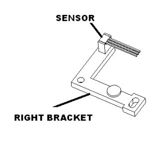
Twist purple, black and blue 30 gauge wires together and cut to 6″ lengths.
Solder the sensor according to the following table
| Connect to | Wire Color |
| Left most pin | PUR |
| Center pin | BLK |
| Right most pin | BLU |
Once soldered tie down wire with a dab of glue and spray accelerator on to dry quickly.
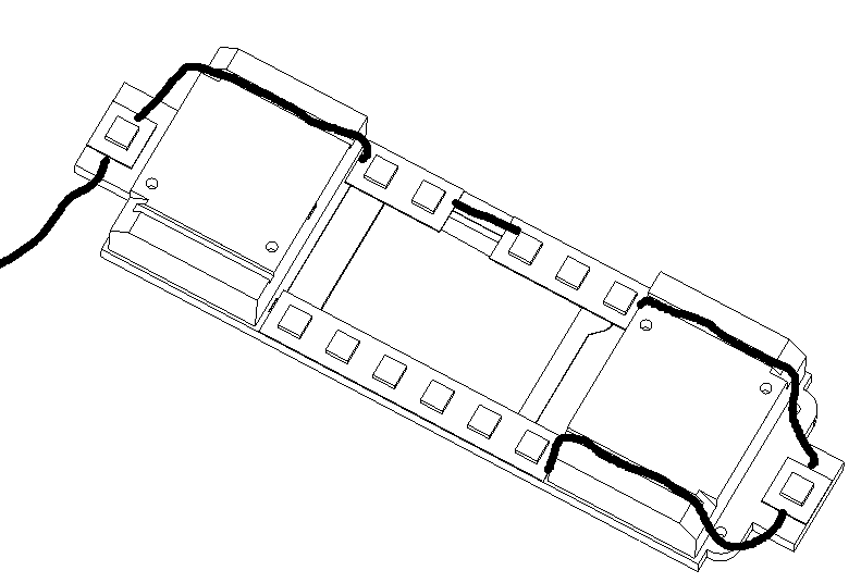
Neopixel harness
Twist black, red and blue 30 gauge wires together and cut according to the following table.
Remove release paper from led strip and cut led strips to lengths shown. Glue and attach them to the chassis as sown. Use the speaker boxes as a guide in placement. Also confirm that the board still fits
| Item | Number LEDs | Wire length |
| Feed wire | NA | 5.5″ |
| Led group 1 | 1 | 3″ |
| Led group 2 | 2 | 1″ |
| Led group 3 | 3 | 3″ |
| Led group 4 | 1 | 3″ |
| Led group 5 | 6 | NA |
Speakers
Cut blue and brown wires to 4″ lengths. Solder wires to speakers brown negative and blue positive.
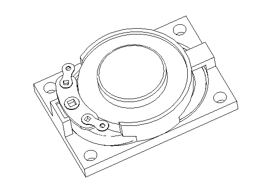
Feed the wires through the holes in the speaker boxes and snap the speaker covers on.
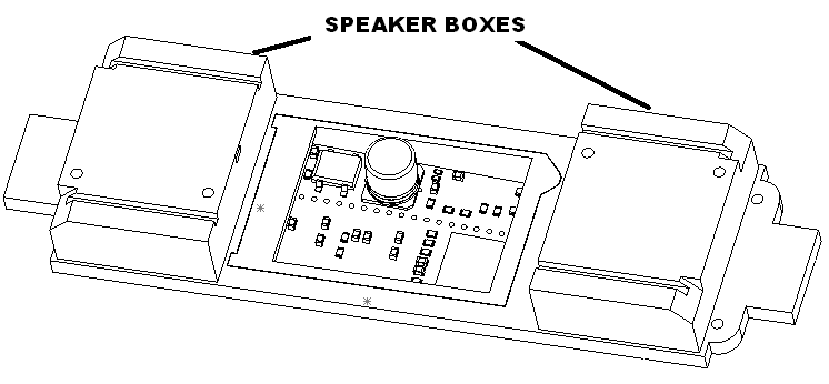
Install the hall effect sensor brackets as shown with 4 M2.3 X 8 screws.
Board connections front side
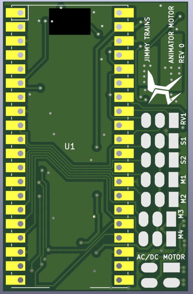
Motor harness connections
Cut the male harness to 2″. Solder the motor harness to the board according to the following table. Be careful the pads are vertical. AC/DC right set of pads, MOTOR left set of pads.
| Connect to | Wire Color |
| AC/DC (round pad 1) | YEL |
| AC/DC (round pad 2) | WHT |
| MOTOR GND (SQ pad 1) | BLK |
| MOTOR Positive (round pad 2) | RED |
Neopixel connections
Solder the neopixel harness to the board according to the following table.
| Connect to | Wire Color |
| M4 GND (SQ pad 1) | BLK |
| M4 5V+ (pad 2) | RED |
| M4 Output (pad 3) | BLU |
Hall effect connections
Twist the blue wires together and the black wires together and tin.
Solder the board according to the following table
| Connect to | Wire Color |
| S2 GND (SQ pad 1) | BLK |
| RV1 3V+ (pad 3) | BLU |
| S1 Input (pad 3) | PUR |
| S2 Input (pad 3) | ORG |
Board connections backside
Turn the board over and solder the remaining items to the board.
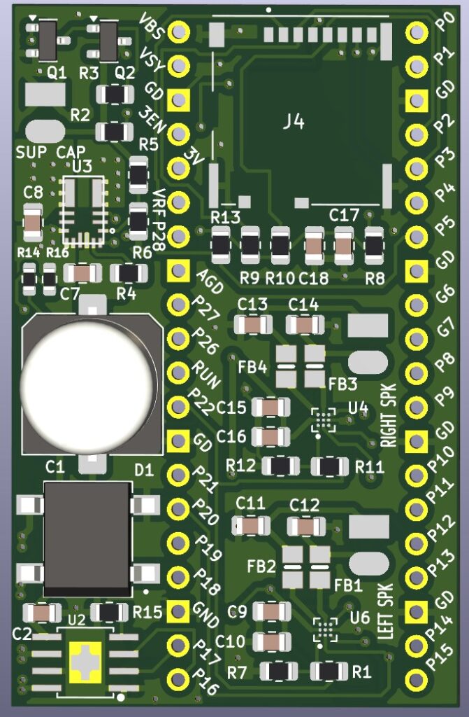
Left and right speaker connections
Feed the speaker through the speaker cover Solder the left and right speaker to the board according to the following table.
| Connect to | Wire Color |
| GND (SQ pad 1) | BRN |
| POS (pad 2) | BLU |
Super cap connections
Bend the wires on super cap to mount. Apply shrink wrap to these wires. Solder the super cap to the board according to the following table.
| Connect to | Wire Color |
| SUP VAP GND (SQ pad 1) | Short lead |
| SUP CAP 5V (SQ pad 2) | Long lead |
Trolley prep
Trolley cover
Lift off the trolley cover. Unsnap the light block. Unplug. Remove the light bulbs so the black head light wire is free.
Remove windows from the top cover.
Trolley chassis
Unscrew the body. Cut the light bulb harness. Cut section out of top from animator.
Cut all tie wraps
Mark the power in with a black marker.
Remove rectifier board and cut the wires to the switch. Reattach.
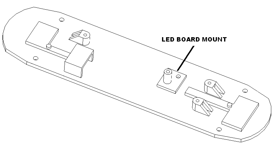
Remove the direction switch. But keep the plastic spacer in place. Attach the led board mount with the screw provided. Attach the board with the screw provided.
Unsolder the led power board and solder to top connections on diode bridge. Black wire on right.
Motor connections
Remove the red wire while holding the pickup rollers in place. Reattach remaining wire.
Unscrew motor.
Unsolder the wires to the motor.
Remove the red and black wires to the unused contact board.
Swap the wire and yellow wire. Yellow to the top.
Extend white wire cut to 5″.
Cut a female harness to 2.0″.
Solder yellow wire to red wire from male plug. Solder to the positive terminal of motor.
Solder white wire to black wire of plug. Solder to the negative terminal of motor.
Reattach motor with the positive lead up.
Solder the remaining yellow and white wire from the male plug to the lower terminals on the bottom of the rectifier board.
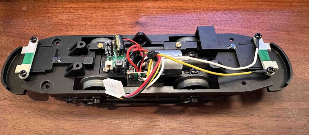
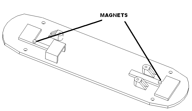
Using the fixture paint the top side of magnets so they are oriented correctly. Sand bottom of magnet and clean. Glue magnets to chassis as shown set aside to dry.
Remove the mold letter “f” near the bumper using a knife. This mark interferes with the bumpers being pushed in.
Assembly
Attach the board to the motor chassis using the countersunk animator clamp one M2.3 X 8 panhead screw.
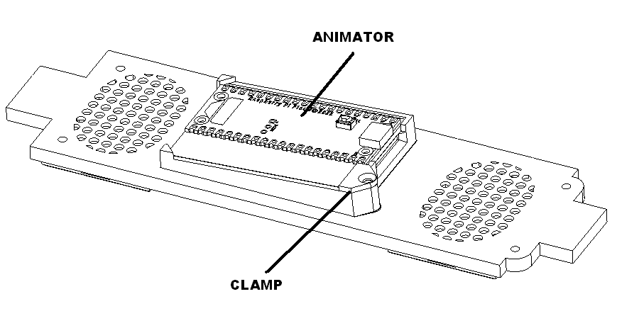
Attach half clamps to the right side as shown using two M2.3 x 8 washer head screws.
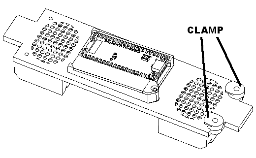
Tuck wires into slots.
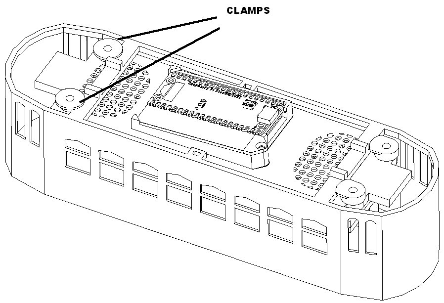
Insert the board assembly into the trolley top first inserting the left end and then tightening the clamps.
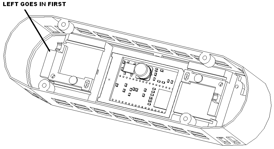
Attach the remain clamps as shown.
Burn in
Set trolley on track and run for an hour.
Packing trolley
Apply instructions label to card inside the trolley.
Put trolley in box.
Tape sd card holder on end.
Put product label on trolley box.
If shipping trolley put trolley in outer box. Put product label on outside.