
Assemblies
Using the drawings below print and gather parts for build.
TT motor drive
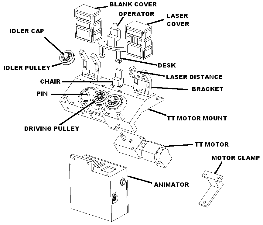
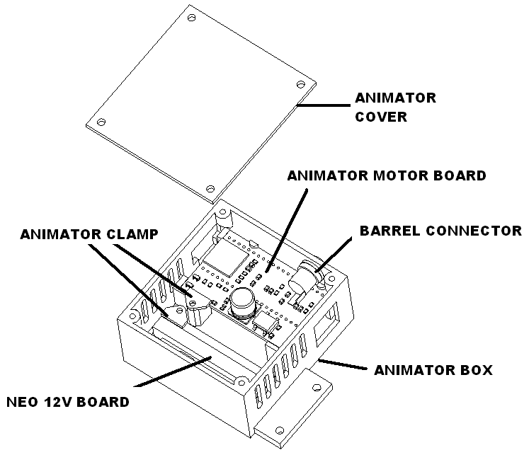
Animator controller
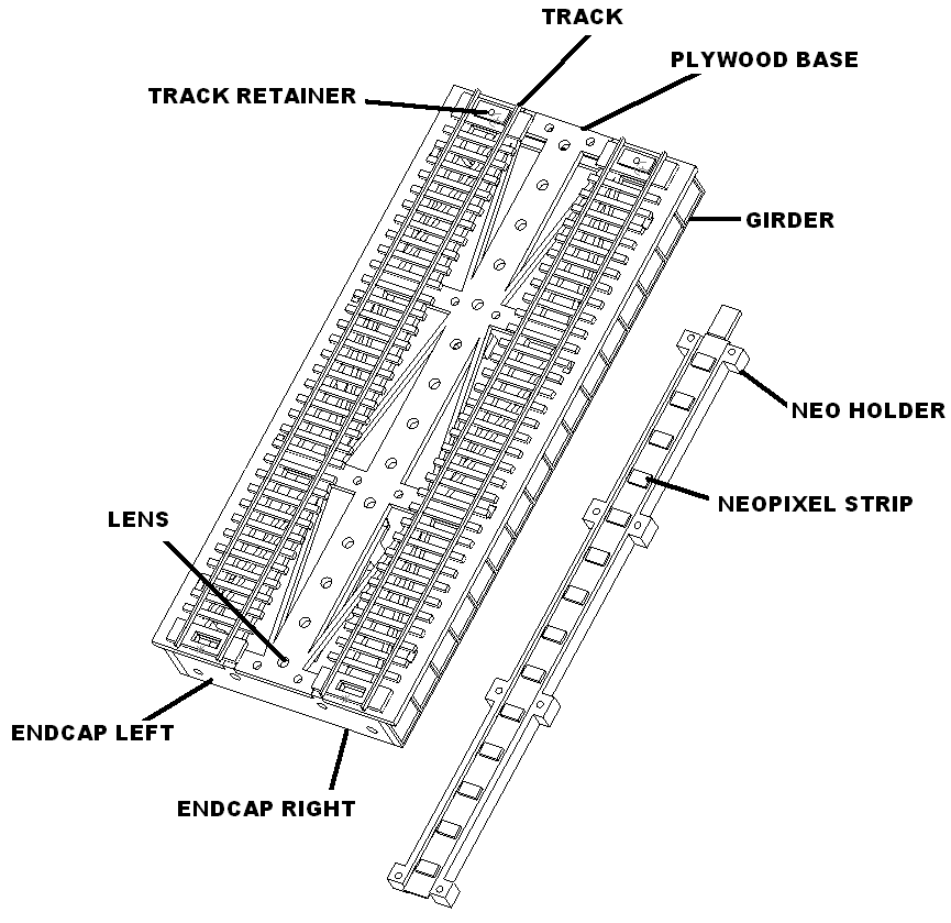
Track section
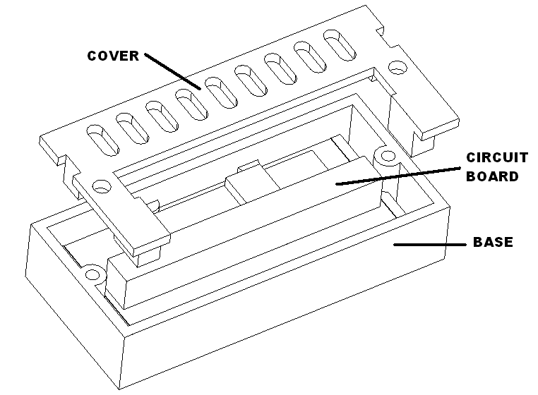
NEO 12V house controllers (only needed for houses)
Plywood pieces (only needed for houses)
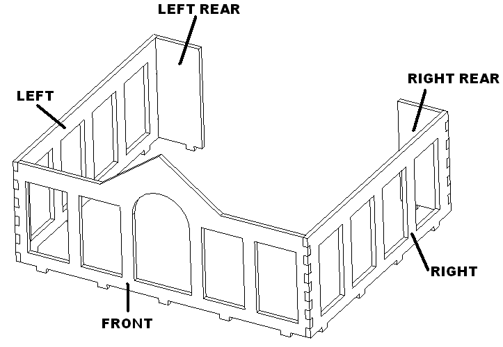
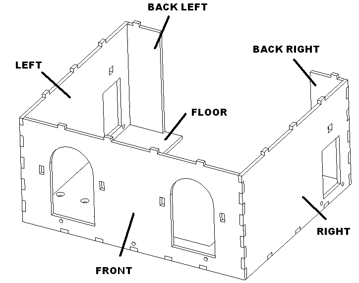
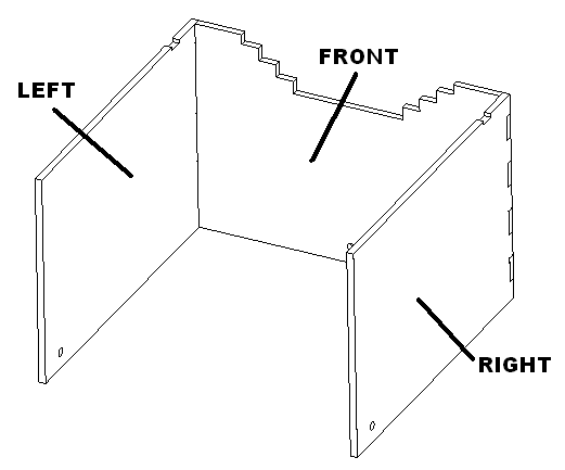
Pre assembly
Threaded inserts
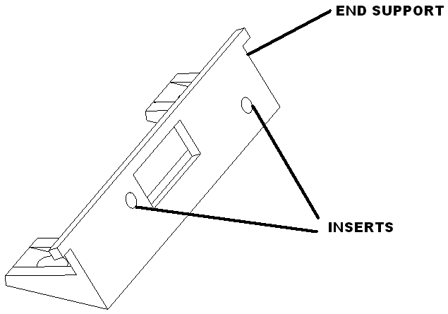
Install one threaded insert in left and right end supports. Repeat for 5 more pairs for a total of 6 which is required for three track sections.
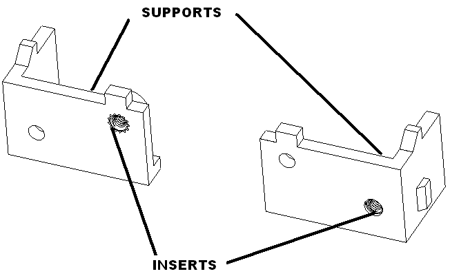
Install four threaded inserts in tt motor mount as shown.
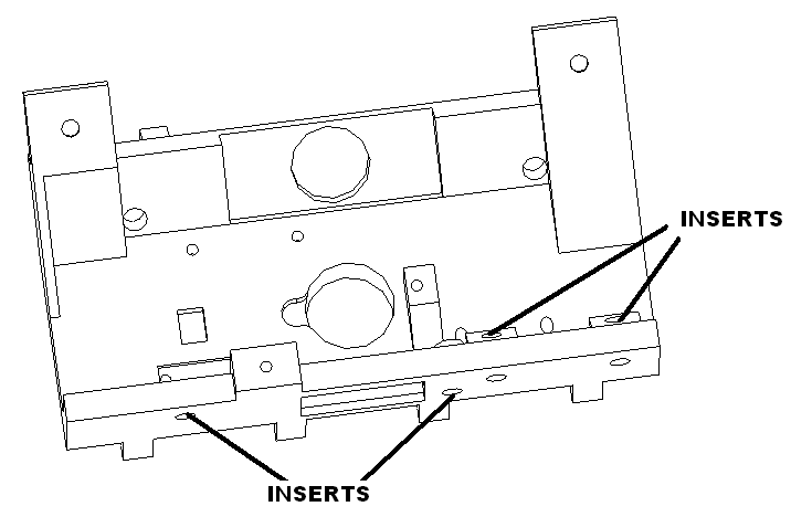
Install two threaded inserts in end support as shown.
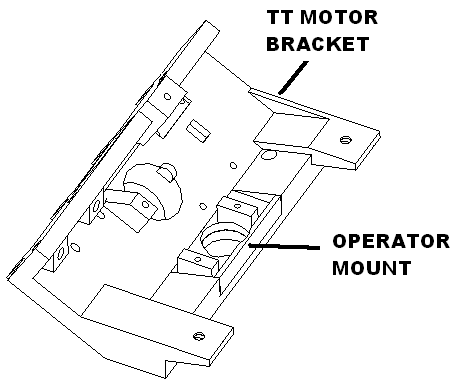
TT Motor bracket
Glue in operator mount as shown.
Glue in pins.
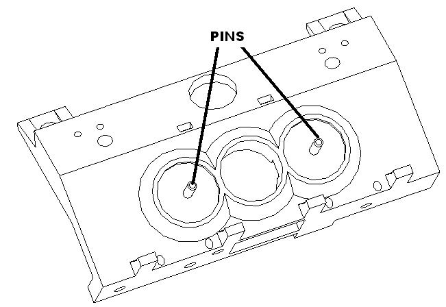
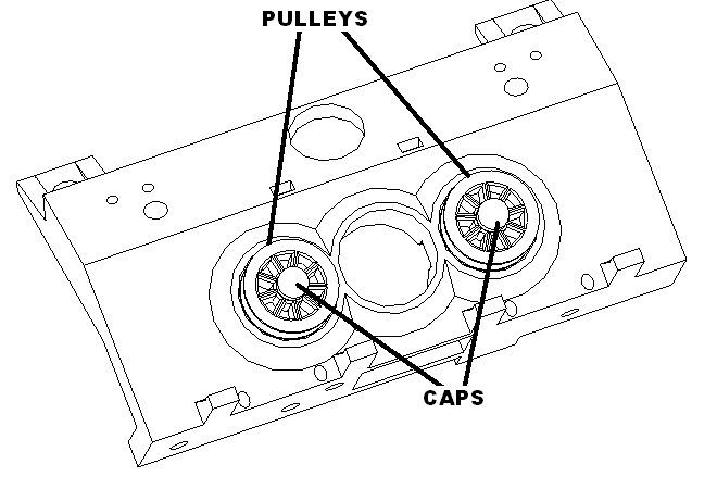
Place pulleys on pins. Glue on rubber caps to retain the pulleys.
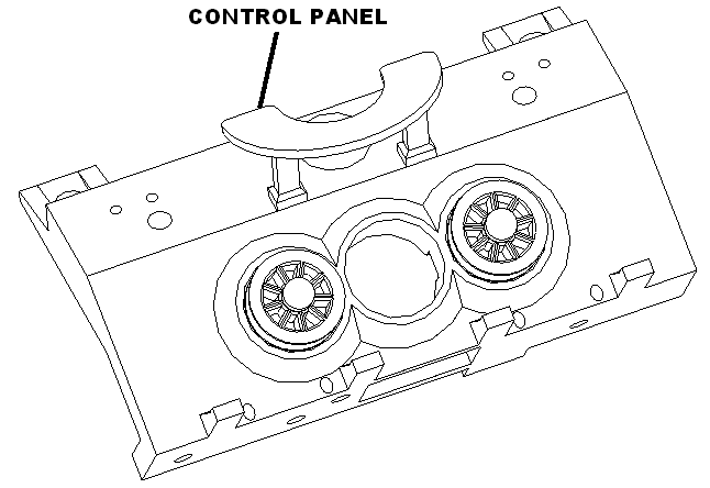
Glue on control panel.
Operator
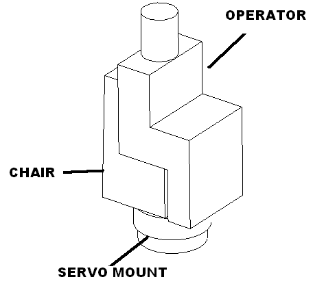
Glue gray chair to gray servo mount, glue operator to chair.
Drive motor
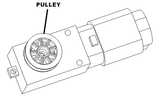
Install pulley on drive motor and fasten with M2.5 x 6 socket head screw.
House windows
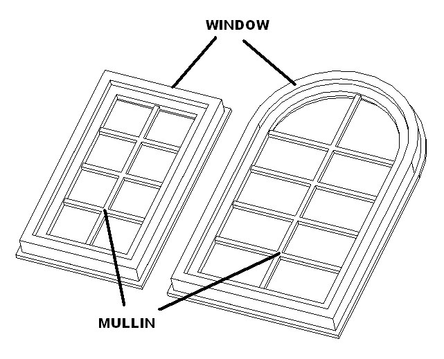
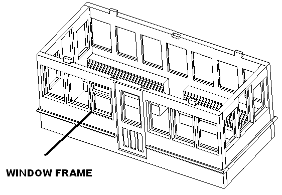
Cut windows with cutter with force 27, passes 5, speed 4, blade depth 6. Install glazing in window, insert frames on top of that. Apply small bead of glue to hold mullions in place.
Switches
Cut two blue wires to 15 inches. Cut two brown wires to 15 inches. Twist the blue wires together and the black wires together and tin. Solder switches to these wires.
Hooks
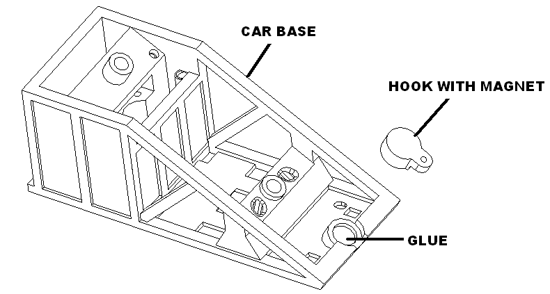
Apply dab of glue as shown on the hook. Using car base attach magnet to it. This insure that its the correct direction. Attach the hook to the car and press. Remove the hook the magnet should now be in place. Clean up any excess glue and set aside to dry.
Car base
Apply dab of glue as shown on car base. Using hook fixture attach magnet to it. This insure that its the correct direction. Attach the hook to the car and press. Remove the hook the magnet should now be in place. Clean up any excess glue and set aside to dry.
Car cabin
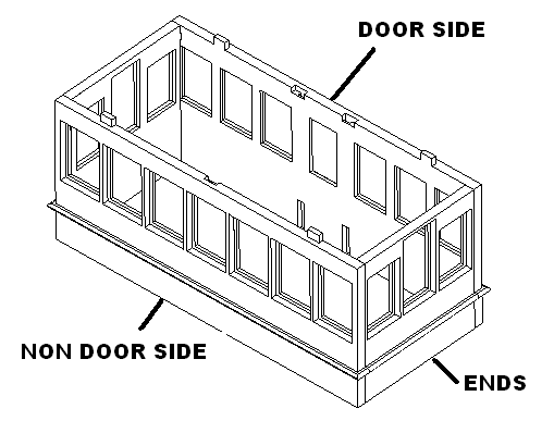
Glue car ends to car sides as shown. Repeat for a second car. Spray on accelerator. Set aside to dry.
Glue benches in by applying glue to the car cabin at ends and under windows for each bench. Then slide them into place. Spray accelerator to set.
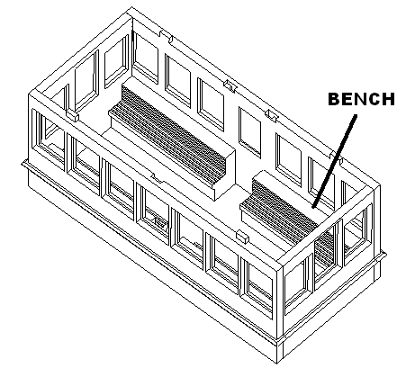
Once everything is dry. Insert window glazing and then frames. Then set in place with glue applied in cracks.
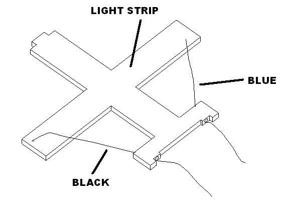
Thread 30 gauge blue and black 5″ wires through light bar as shown. Attach a three light strip to the light bar as shown. Blue is positive, black is negative.
Track module assembly
Glue left and right ends to plywood base as shown. Then glue left and right girder on. Make sure assembly is square using square block and then set with accelerator.
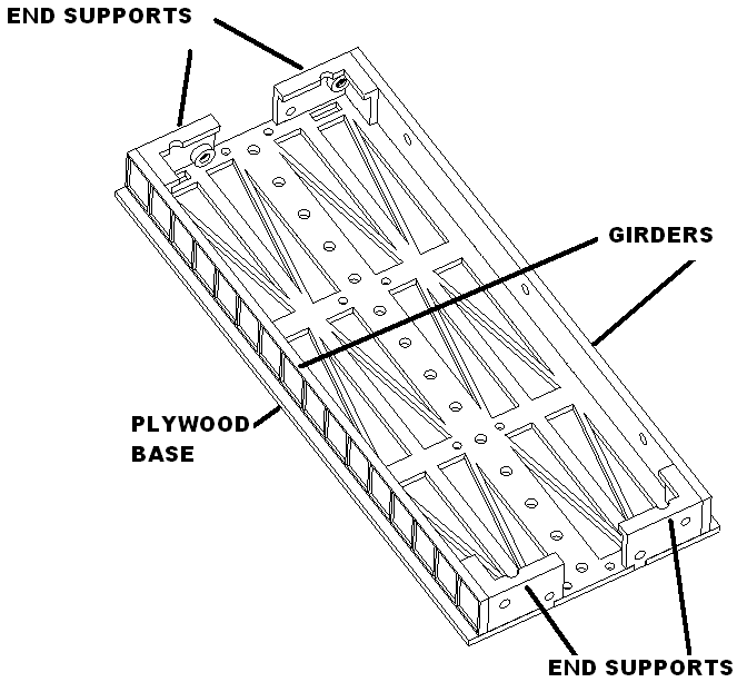
Paint plywood black. Set aside to dry.
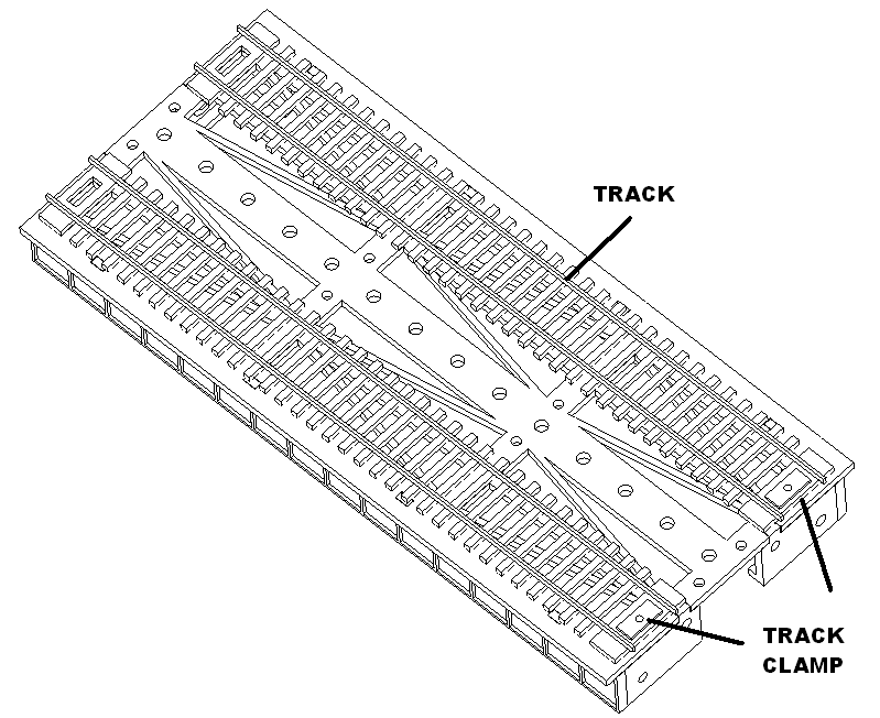
Install track sections using track retainers and M2.3 X 6 washer head screws. Do not tighten screws entirely.
Glue lenses in.
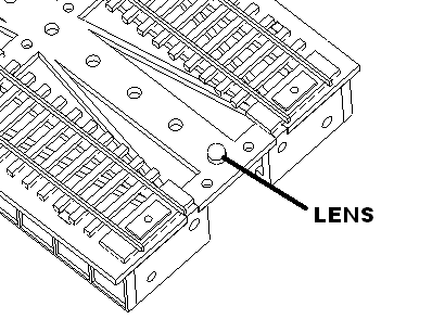
Cut three strips of neopixels 14 lights. Cut three pin harness 3″ from male end. Keep the female end.
Solder male harness on end shown then solder each assembly together with three 1″ wires. Then solder female harness on end.
Shape led strips into neo holders.
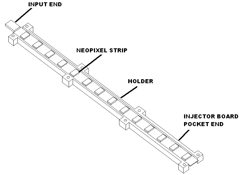
Assemble all three track sections and attach end support with M. Make sure they are assembled as shown. Use the double cross on the left as a guide. Install neo assembly in using M2.3 X 6 screws.
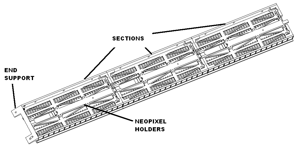
Animator controller assembly
Remove the MOSFET Q1 and Q2 from board. Then solder a wire from super cap positive to VSYS.
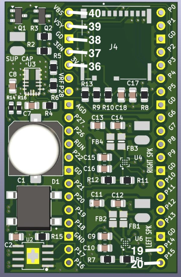
Board connections front side
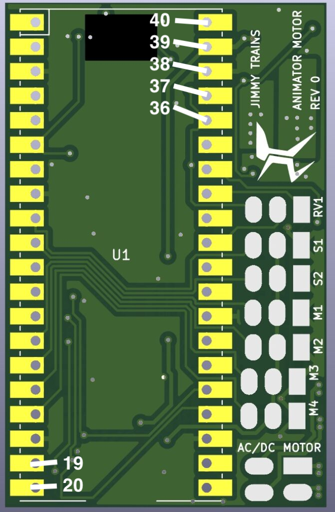
Power supply connections
Route the female barrel connect through the lower left hole of animator case. Solder to the board according to the following table.
| Animator Connection | Wire Color |
| Power in GND (square pin 1) | BRN |
| Power in 12V+ (pin 2) | BLU |
Switch connections
Feed wires through lower left hole in controller case. Solder the board according to the following table
| Animator Connection | Wire Color |
| S1 GND (SQ pad 1) | BRN |
| S1 Input (pad 3) | BRN |
| S2 GND (SQ pad 1) | BLU |
| S2 Input (pad 3) | BLU |
Operator servo connection
Cut three pin female end to 6″. Label it operator. Feed wires through the top hole in controller case. Solder to the to the board according to the following table.
| Animator Connection | Wire Color |
| M1 GND (SQ pad 1) | BRN |
| M1 5V+ (pad 2) | RED |
| M1 Output (pad 3) | YEL |
Upper house neopixel connections
Cut three pin female end to 6″. Label it upper house. Feed wires through lower side hole in controller case. Solder to the to the board according to the following table.
| Animator Connection | Wire Color |
| M2 GND (SQ pad 1) | BLK |
| M2 5V+ (pad 2) | RED |
| M2 Output (pad 3) | WHT |
Track neopixel connections.
Cut three pin female end to 6″. Label it track. From what remains of the wires cut a section 6″ long. Solder this to the animator board using the following table.
| Animator Connection | Wire Color |
| M4 GND (SQ pad 1) | BLK |
| M4 5V+ (pad 2) | RED |
| M4 Output (pad 3) | WHT |
Solder this to the city lights board using the following table.
| City lights board connection | Wire Color |
| GND input | BLK |
| Signal input | WHT |
| 5V+ input | RED |
Solder to the to the city lights board according to the following table. Feed the female connection through top hole in controller case.
| City lights board connection | Wire Color |
| GND output | BLK |
| Signal output | WHT |
| 5V+ output | RED |
Cars power
Cut 30 gauge black and yellow wires to 7 inches. Twist together. Cut 30 gauge black and orange wires to 10 inches. Twist together. Solder this to the city lights board using the following table. Feed through the top hole in controller case.
| City lights board connection | Track connection | Wire Color |
| GND (pin 1) | Left track left rail | BLK |
| 12V+ (pin 2) | Left track right rail | YEL |
| GND (pin 3) | Right track left rail | BLK |
| 12V+ (pin 4) | Right track right rail | ORG |
Motor harness connections
Cut the male motor harness to 8″. Feed wires through top hole in controller case. Solder the motor harness to the board according to the following table. Feed through the top hole in controller case.
| Pico Connection | Wire Color |
| Motor – (square pad) | BLU |
| Motor + (pad 2) | GRN |
| 3V+ (pico pin 36) Note: Join this with laser also | YEL |
| GND (pico pin 38) | BRN |
| A (pico pin 19) | ORG |
| B (pico pin 20) | RED |
Laser sensor connections
Cut black, red, yellow and purple wires to 10″. Solder to the board according to the following table. Feed through the top hole in controller case.
| Pico Connection | Laser sensor | Wire Color |
| 3V+ (pico pin 36) | VIN Note: Join with motor also | RED |
| GND (pico pin 3) | GND | BLK |
| SCL (pico pin 2) | SCL | YEL |
| SDA (pico pin 1) | SDA | PUR |
Board connections backside
Turn the board over and solder the remaining items to the board.
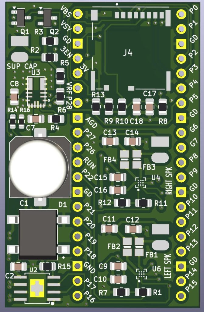
Left and right speaker connections
Cut white and gray wires to 15″. Tin and twist together. Repeat. Label left and right speakers.
Solder the left and right speaker to the board according to the following table. Feed through the top left hole in the case.
| Animator Connection | Wire Color |
| GND (SQ pad 1) | GRY |
| POS (pad 2) | WHT |
Pulley drive unit assembly
Feed the track wires through the track holes as shown. Feed the track female connector through the track hole.
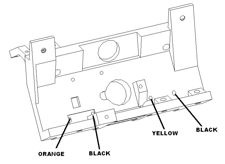
Attach the motor using motor bracket and 3 M2.6 X 8 washer head screws and one M2.6 X 8 pan head screw. Feed the laser sensor wire through the hole.
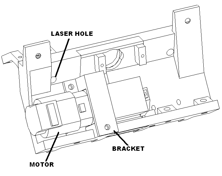
Attach the servo motor to the pulley base with screws provided.
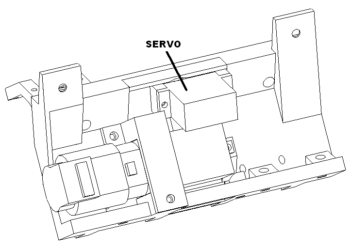
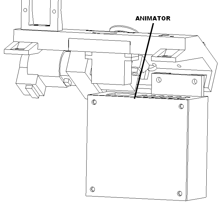
Attach the animator controller to the pulley base with 2 M3 X 8 socket head screws.
Mount laser bracket, left and right with M2.3 X 8 washer head screws. Mount laser board to right bracket with four little servo screws.
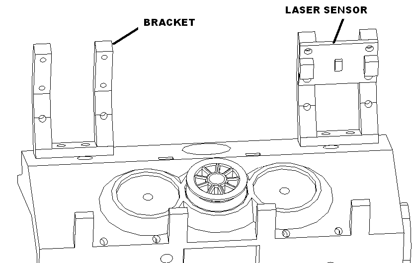
Solder the connections to the laser sensor using the following table.
| Pico Connection | Laser sensor | Wire Color |
| 3V+ (pico pin 36) | VIN | RED |
| GND (pico pin 3) | GND | BLK |
| SCL (pico pin 2) | SCL | YEL |
| SDA (pico pin 1) | SDA | PUR |
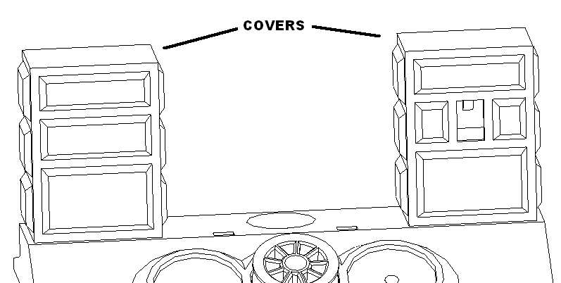
Mount cover with hole over laser sensor and cover without hole on the left bracket.
Screw the drive bracket to the assembly was shown using 2 M3X8 socket head screws.
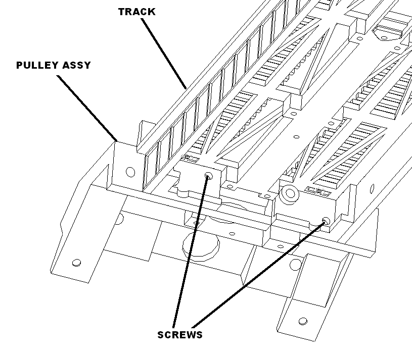
Solder the connections to the track, from left to right, black, yellow and black, orange.
Test the assembly. If working bundle up the wires and tywrap them.
Car assembly
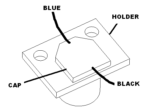
Glue in cap into cap holder as shown. Solder a 6 inch blue wire to the positive, the tapered side and a black wire to the negative square side. Repeat.
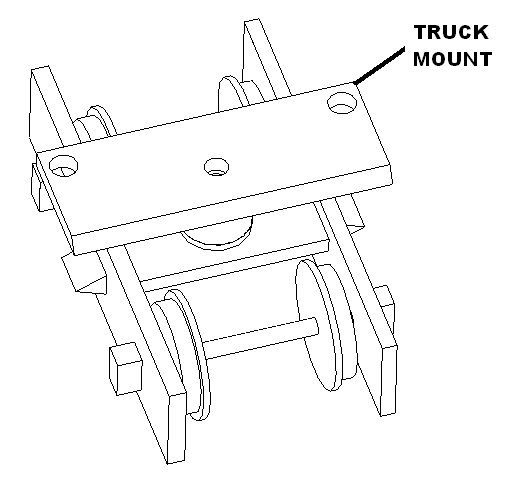
Install two trucks to the front truck mount using two M2.3 X 6 pan head screws.
Left car
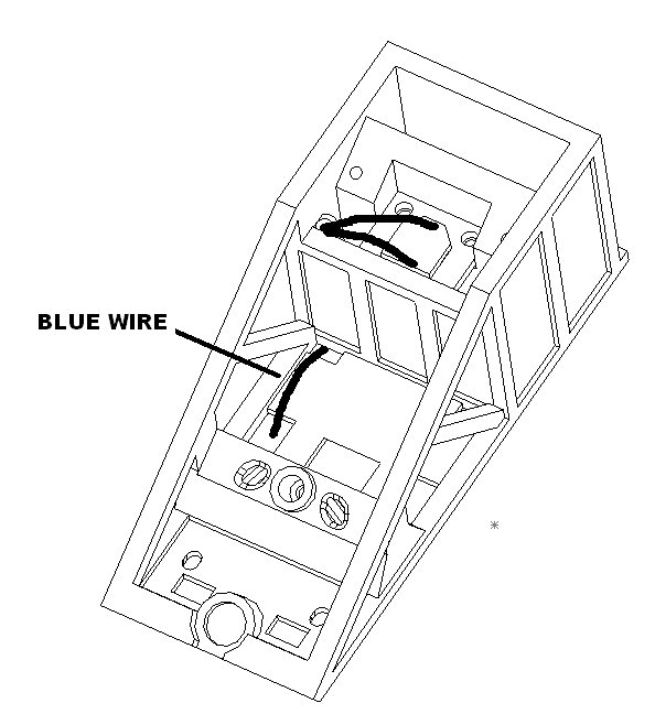
Installed the cap assembly into car bottom using 2 M2.3 X 6 pan head screws. Route the blue wire to the front truck area on the left.
Cut away the front section of the front truck. Route the truck wire through the wire hole on the left. Place the truck into the counter bore with the conducting wheels on the right as shown and fasten with one M2.3 X 6 pan head screw.
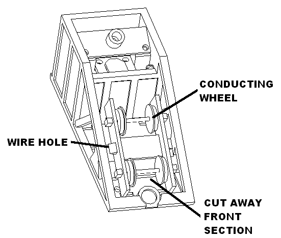
Mount the rear truck with the conduction wheel to the left with two M2.3 X 8 pan head screws. Feed the wire down the hole.
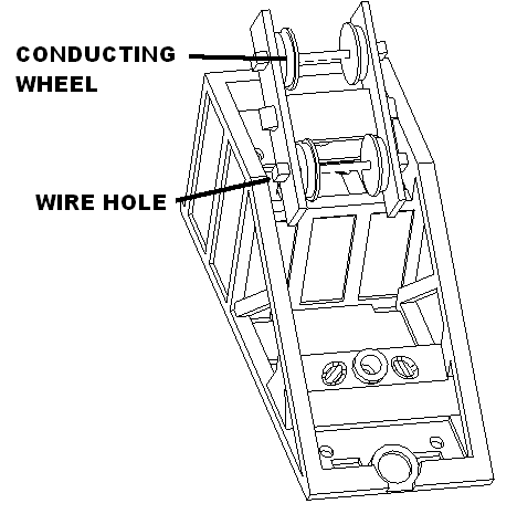
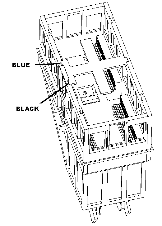
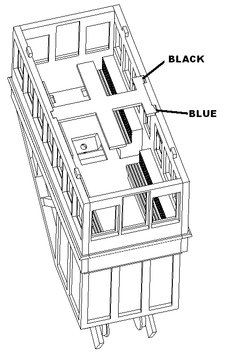
Route the blue and black wire from the light bar through the holes around the doors. Bundle all the blue wires together and solder. Bundle all the black wires together and solder. Mount the car body on the car base tucking the wires under the benches and fasten with 4 M2.3 X 8 screws.
Right car
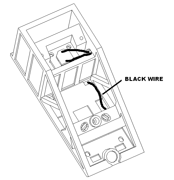
Installed the cap assembly into car bottom using 2 M2.3 X 6 pan head screws. Route the black wire to the front truck area as shown.
Cut away the front section of the front truck. Route the truck wire through the wire hole on the right. Place the truck into the counter bore with the conducting wheels on the left as shown and fasten with one M2.3 X 6 pan head screw.
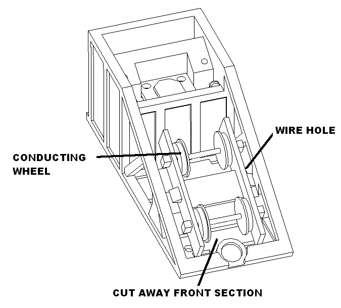
Mount the truck with the conduction wheel to the right with two M2.3 X 8 pan head screws. Feed the wire down the hole.
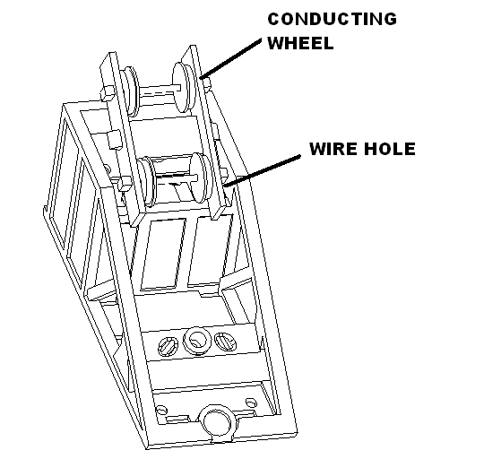
Route the blue and black wire from the light bar through the holes around the doors. Bundle all the blue wires together and solder. Bundle all the black wires together and solder. Mount the car body on the car base tucking the wires under the benches and fasten with 4 M2.3 X 8 screws.
Magnetic hook assembly
Cut 65 lb fishing thread using a sharp scissors to 84.5 center meters. Tie one to the non adjustable hook as shown. Make sure the thread come out at the top.
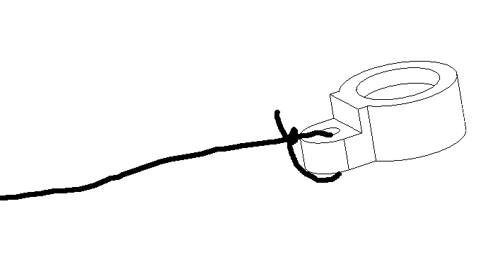
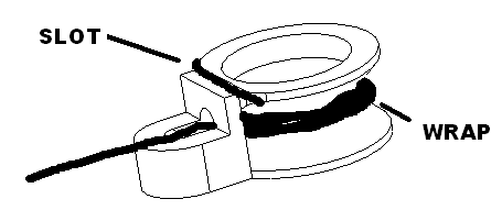
Repeat this for the adjustable end. Insert in the hole as shown with the cable on top. Wrap several times and pull down into the slot. After a few wraps the length to 74.5 cm magnet center to magnet center. Once adjusted keep wrapping until the spool is pretty full. Finish off with one last insert in the slot and cut remainder.
Lower house assembly
Gluing pieces
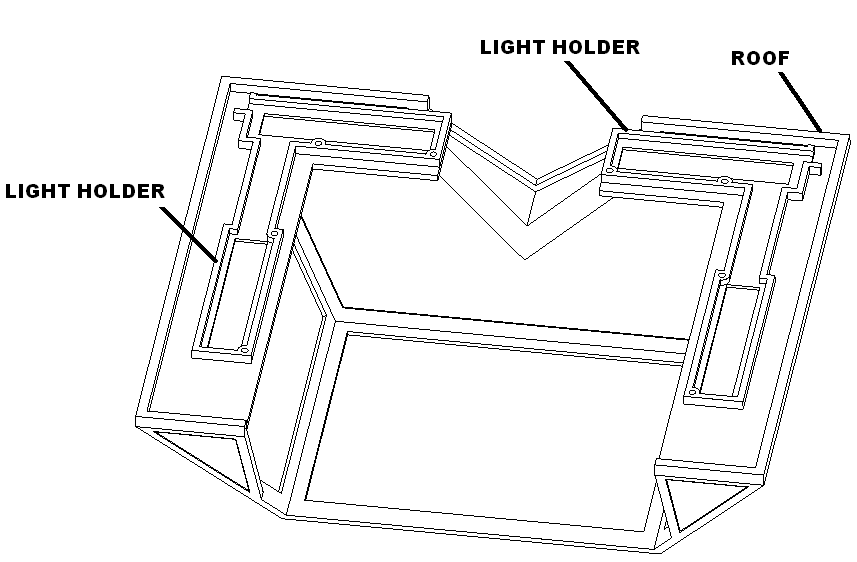
Glue and screw light holders to bottom of roof assembly as shown using 4 M2.3 x 6 screws. Hold pieces down spray with accelerator. Hold till glue set. Set aside to dry.
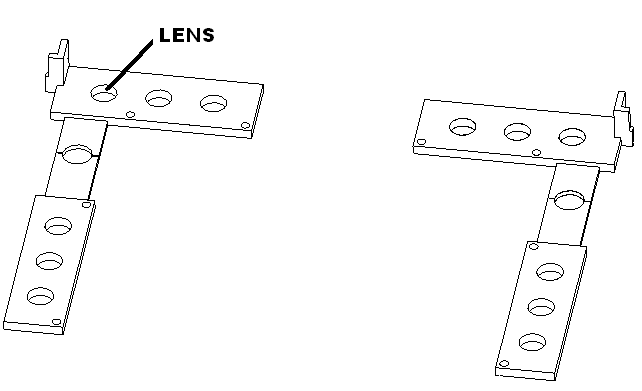
Glue twelve lenses into lens holders.
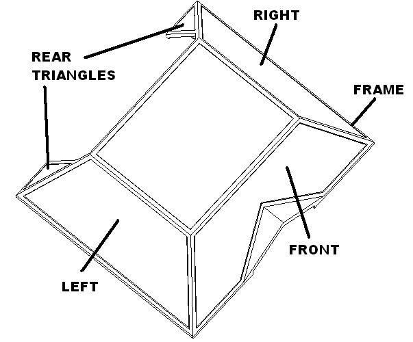
Using wood glue, glue the upper assembly left to the front as shown tape corner to set, repeat with the right, left, left rear and right rear. Set aside to dry.
Glue the left to the lower assembly front as shown tape corner to set, repeat with the right, left, left rear and right rear. Glue the floor on.
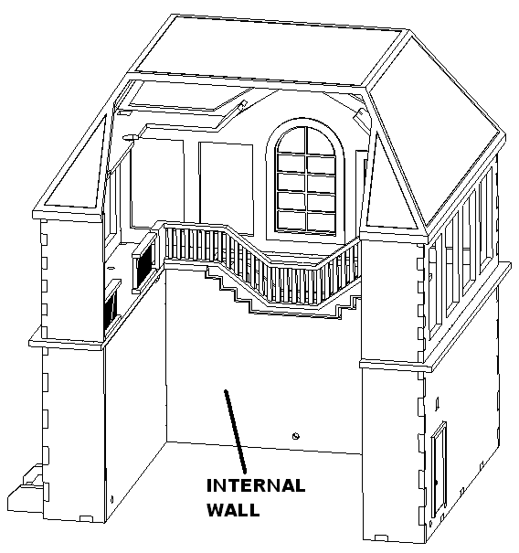
Glue the left internal wall to the front as shown tape corner to set, repeat with the right. Set aside to dry.
Paint Granite grey
Mix 4 parts white with black to make granite grey.
Paint the inside of the upper assembly granite grey.
Paint the outside of the lower assembly granite grey.
Paint the car floor on the bottom granite grey within the tab holes.
Paint shingle bottoms granite gray leave room on border for glue.
Paint the inside of the internal wall. Paint the front of the internal wall facing the doors.
Paint Concrete grey
Mix 2 parts black with white to make dark concrete grey.
Paint the car floor on the bottom granite grey outside the tab holes. Let dry. Paint the entire top.
Paint all shingle tops.
Paint True red
Paint the outside of the upper upper true red.
Final assembly
Glue the shingle panels into the roof. Set aside to dry.
Glue the car floor to the lower assemble using super glue. Then glue the upper wall assembly on. Set aside to dry.
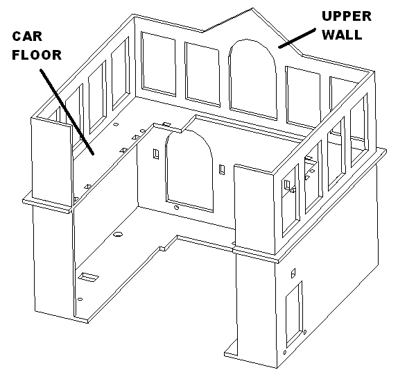
Glue stair railing into notches in car floor. Glue stairs below the stair railing.
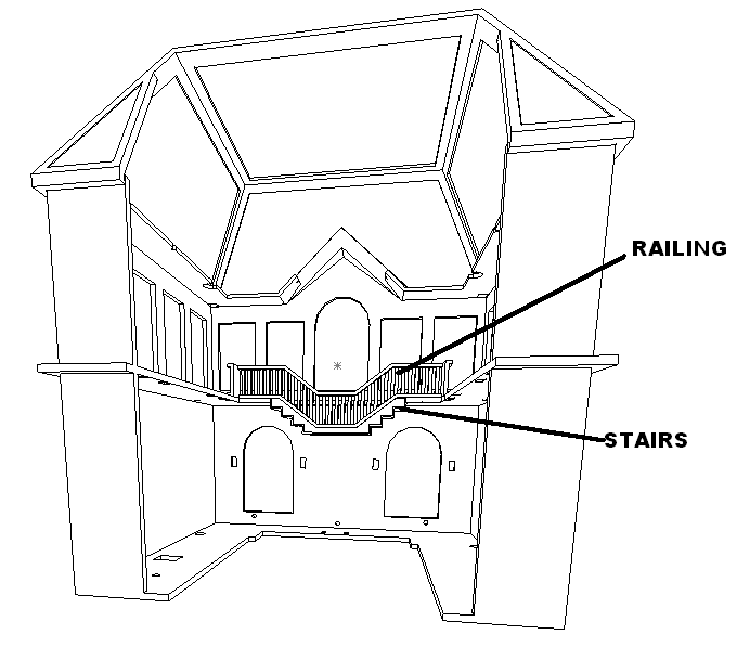
Glue in two window frames in the front left and right corner. Glue the cable guides in the corner.
House electronics
Cut 18″ cable extension in half. Label the female end “LOWER”, label the male end “LOWER. Cut 18” of yellow, purple, two blues, and two blacks 30 gauge wire. Combine black, blue, orange and yellow wires together and twist. Combine black, blue and purple wires together and twist.
Solder these wires to the input and output of the NEO-HV board using the following table.
| Board connection | Wire Color |
| 5V | RED |
| Signal in | WHT |
| GND | BLK |
| 5V | BLU 2X |
| Signal out | YEL |
| GND | BLK 2X |
| Combine these wires and shrinkwrap | ORG and PUR |
Insert in circuit board into base as shown. Attach cover with 2 M2.3 X 6 screws.
Install all the lights and solder to the neo hv board using the following connections.
| Light | Board connection | Wire Color | Length |
| Operators Left gate | J3 GND | BLK | 13″ |
| Operators Left gate | J3 12V | BRN | 13″ |
| Operators Right gate | J4 GND | BLK | 18″ |
| Operators Right gate | J4 12V | GRN | 18″ |
| Stair area | J5 GND | BLK 2X | 13″ left, 18″ right |
| Stair area | J5 12V | BLU 2X | 13″ left, 18″ right |
Insert left gate wire through cone of the left gate and solder, insert right gate wire through cone and solder.
| 5V | BLU |
| Signal input | YEL |
| GND | BLK |
| Signal output | ORG |
Insert right gate wire through cone for right gate and solder to gate.
| 5V | BLU |
| Signal input | ORG |
| GND | BLK |
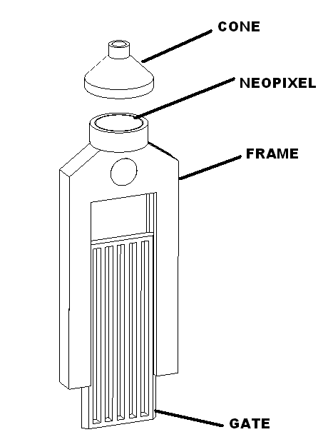
Mount gates to building using 4 M2.3 x 8 pan head screws. Glue railings to building as shown.
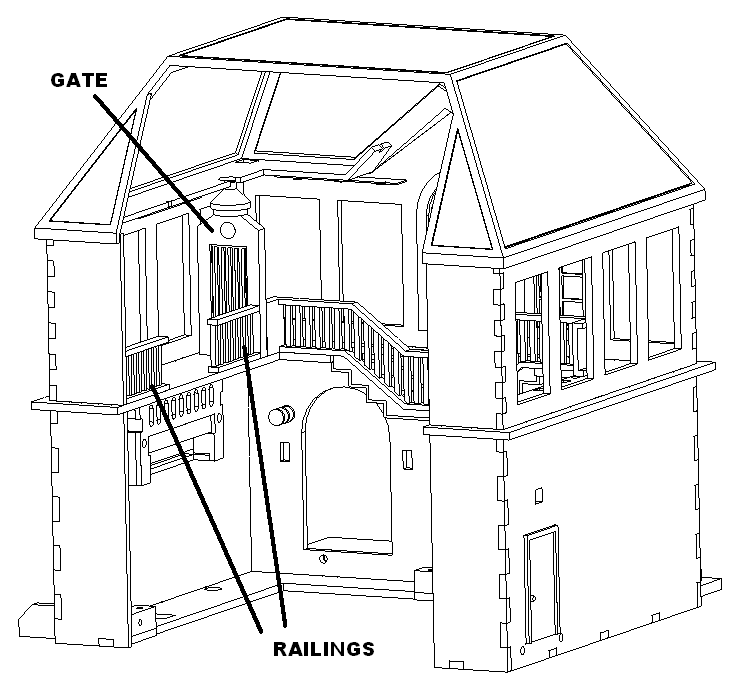
Mount the lights for the ticket booth.
| Light | Board connection | Wire Color | Length |
| Ticket booth | J6 GND | BLK | 6″ left, 5″ between |
| Ticket booth | J6 12V | RED | 6″ left, 5″ between |
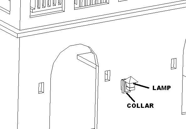
Drill wire hole in collar using #54 drill. Glue a coach lamp into their collar. Glue this into the holes in the front. Repeat three times. Bundle pairs of lamps and strip wire ends.
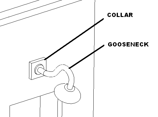
Drill wire hole in collar using #54 drill. Glue a gooseneck into their collar and install above utility doors on the sides. Bundle pairs of lamps and strip wire ends.
Install all the lights and solder to the neo hv board using the following connections.
| Light | Board connection | Wire Color | Wire length |
| Goose necks | J2 GND | BLK 2X | 10″ left, 24″ right |
| Goose necks | J2 12V | RED 2X | 10″ left, 24″ right |
| Carriage lamps | J1 GND | BLK 4X | 10″ left, 14″ right |
| Carriage lamps | J1 12V | RED 4X | 10″ left, 14″ right |
Mount the light controller with 2 M2.3 x 8 pan head screws. Mount 2 light connectors block as shown with some glue.
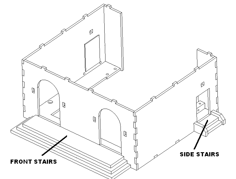
Attach front stairs and side stairs using 7 M2.6 X 8 screws.
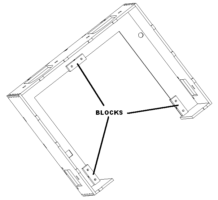
Attach clamp the blocks using M2.3 X 8 screws.
Glue windows and doors into assembly. Glue the roof to the upper assembly.
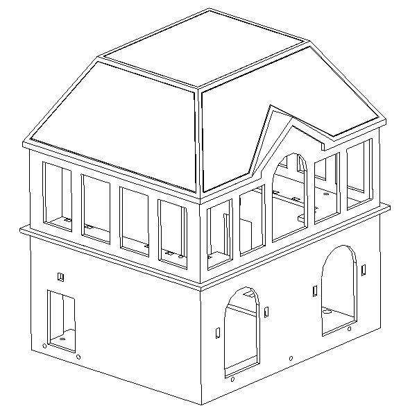
Test assembly and make sure all lights work.
Install electronics cover using 3 M2.3 X 9 pan head screws.
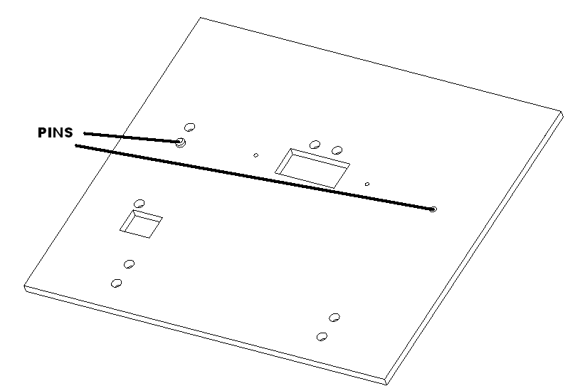
Install two pins in laser cut base as shown.
Upper house assembly
Gluing pieces
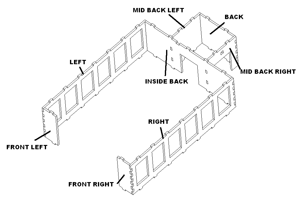
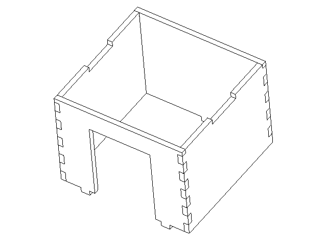
Using wood glue, glue the upper assembly front left, to left, inside back, right, front right. Then glue the mid back left to the back, to the mid back right. Then glue it into the inside back. Set aside to dry.
Glue the upper stairs box together as show. Set aside to dry.
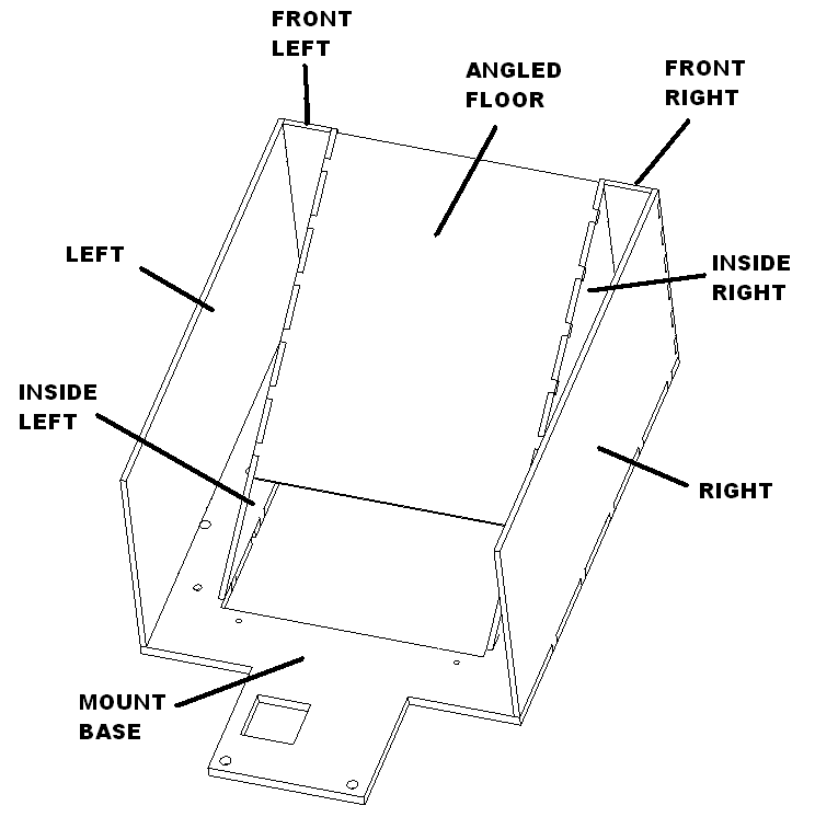
Place the mount base upside down as shown. Glue the inside left first, then the front left and finally the left. Repeat for the right parts. Set aside to dry.
Paint Granite grey
Mix 4 parts white with black to make granite grey.
Paint the inside of the upper assembly granite grey.
Paint the outside of the lower assembly granite grey.
Paint the inside of the upper stairs box granite grey.
Paint shingle bottoms granite gray leave room on border for glue.
Paint Concrete grey
Mix 2 parts black with white to make dark concrete grey.
Paint the angle floor on the bottom granite grey within the tab holes.
Paint all shingle tops.
Paint True red
Paint the outside of the upper upper and stairs box true red.
Final assembly
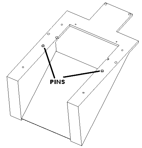
Glue in the locating pins as shown.
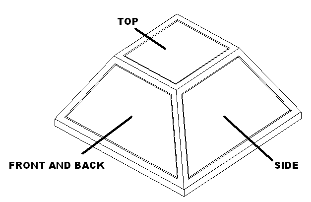
Glue the shingle panels into the roof. Set aside to dry.
Glue windows and doors into assembly.
Glue the car floor to the lower assembly using super glue. Then glue the upper wall assembly on.
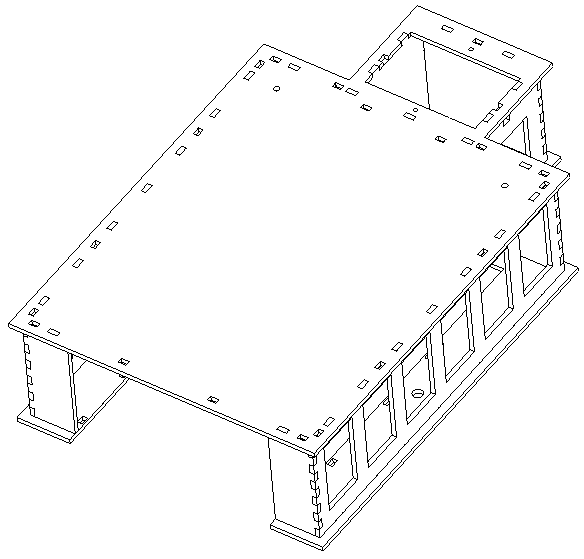
House electronics
Cut 18″ cable extension in half. Label the female end “UPPER”, label the male end “UPPER. Cut xxx” of yellow, purple, orange, two blues, and two blacks 30 gauge wire. Combine black, blue, yellow and orange wires together and twist. Combine black, blue and purple wires together and twist.
| Board connection | Wire Color |
| 5V | RED |
| Signal in | WHT |
| GND | BLK |
| 5V | BLU 2X |
| Signal out | YEL |
| GND | BLK 2X |
| Combine these wires and shrinkwrap | ORG and PUR |
Solder these wires to the input and output of the NEO-HV board using the following table.
Insert in circuit board into base as shown. Attach cover with 2 M2.3 X 6 screws.
Install all the lights and solder to the neo hv board using the following connections.
| Light | Board connection | Wire Color | Length |
| Operators Left gate | J3 GND | BLK | 13″ |
| Operators Left gate | J3 12V | BRN | 13″ |
| Operators Right gate | J4 GND | BLK | 13″ |
| Operators Right gate | J4 12V | GRN | 13″ |
| Operator Area | J5 GND | BLK 2X | 13″ |
| Operator Area | J5 12V | BLU 2X | 13″ |
Insert left gate wire through cone of the left gate and solder, insert right gate wire through cone and solder.
| 5V | BLU |
| Signal input | YEL |
| GND | BLK |
| Signal output | ORG |
Insert right gate wire through cone for right gate and solder to gate.
| 5V | BLU |
| Signal input | ORG |
| GND | BLK |
Mount gates to building using 4 M2.3 x 8 pan head screws.
Run the light cables for the balcony lights through the hex rubber bases into the light channel.
| Light | Board connection | Wire Color | Wire length |
| Carriage lamps | J1 GND | BLK 2X | 13″ |
| Carriage lamps | J1 12V | WHT 2X | 13″ |
Mount the lights for the stair case.
| Light | Board connection | Wire Color | Length |
| Stair case | J6 GND | BLK | 6″ |
| Stair case | J6 12V | RED | 6″ |
Drill wire hole in collar using #54 drill. Glue a gooseneck into their collar and install above entrance door.
Install all the lights and solder to the neo hv board using the following connections.
| Light | Board connection | Wire Color | Wire length |
| Goose necks | J2 GND | BLK | 10″ |
| Goose necks | J2 12V | RED | 10″ |
Mount the light controller with 2 M2.3 x 8 pan head.
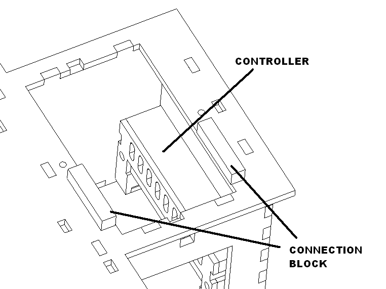
Place the stairs block on the balcony.
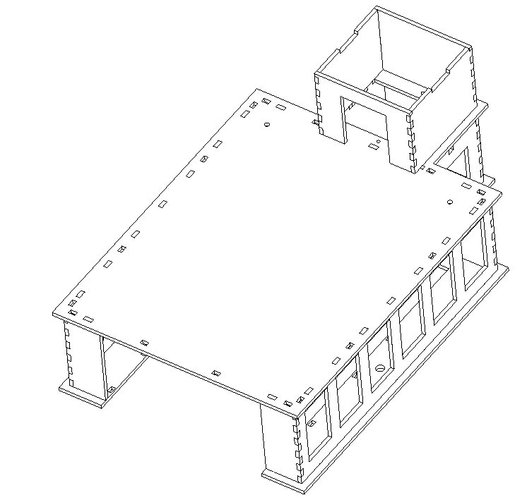
Mount the railings as shown using super glue.
Test assembly and make sure all lights work.
Packaging Track module
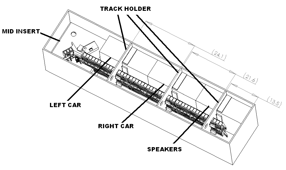
Place the left car in its mid insert and place in the box.
Place the right car in its mid insert and place into the box.
Place two speakers in the speaker mid insert and tape place into the box.
Place the track inserts around the track assembly place as shown tape down.
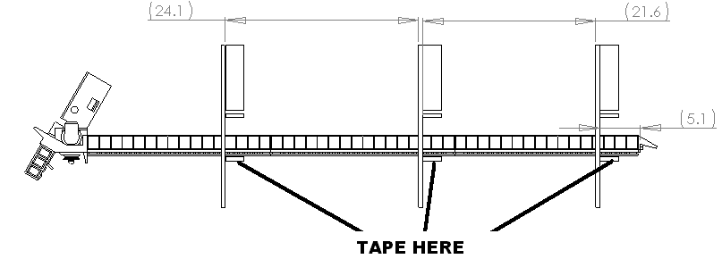
Install the mid insert on the left side, tape these three boxes together and place into the 36 inch box. Place the track into the box. Tape the track holders down.
Make a 5 X 9 and 5 X 5 bubble wrap bag.
Put power supply, 2 car cables, incline figure, transformer cable into 5 x 9 bag. Tape shut and attach on the left back wall.
Gather wires from controller with quick connects on speaker wires and put in 5 X 5 bag. Tape down on the mid insert.
Packaging Lower house and stand
Tape stand together as shown.
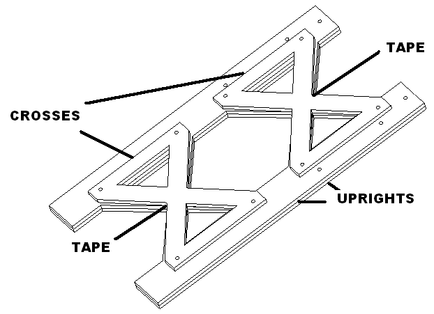
Place cardboard on top and tape. Tape blocks to notches in cardboard on both sides. Tape screw bag down.
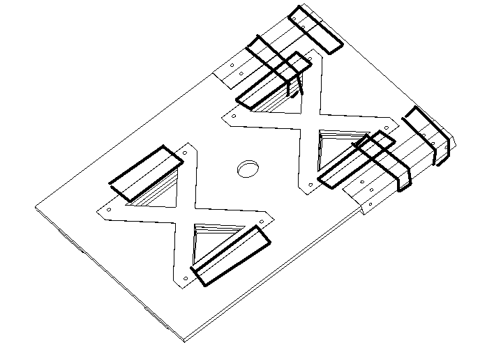
Insert into box.
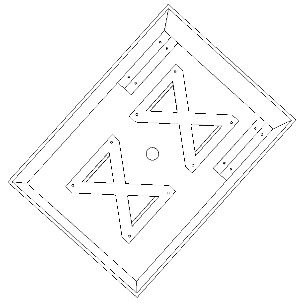
Tape house to its mounting base. Tuck the electrical wire in and tape down.
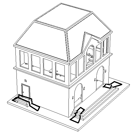
Tape cardboard ends to the base as shown. Repeat on the far side too.
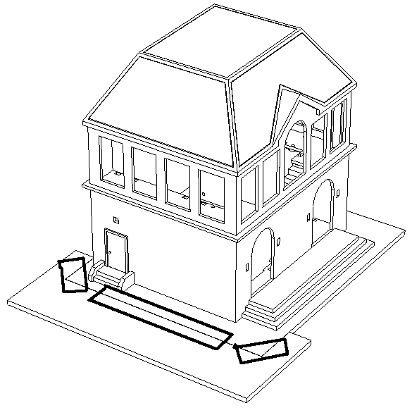
Carefully place house in box.
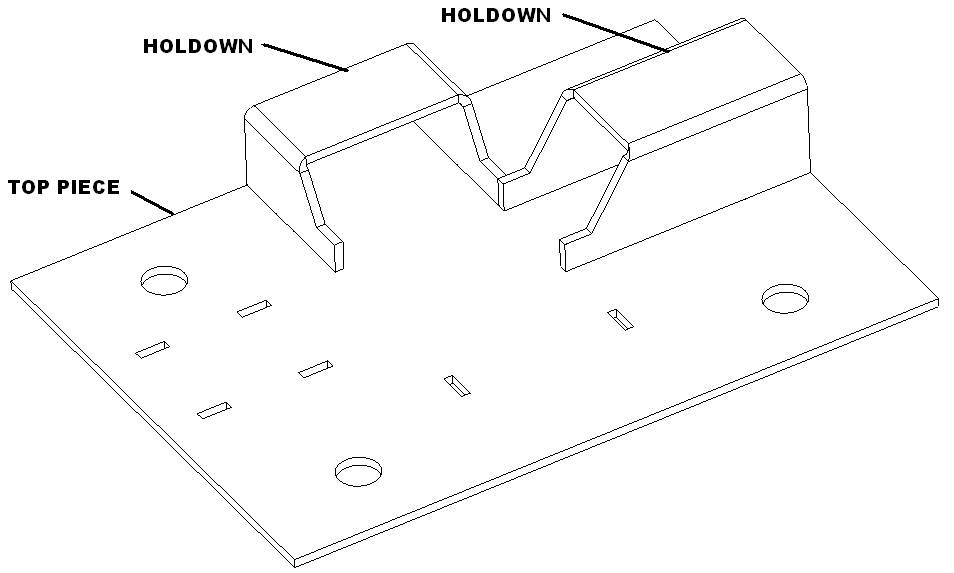
Tape hold downs to top piece.
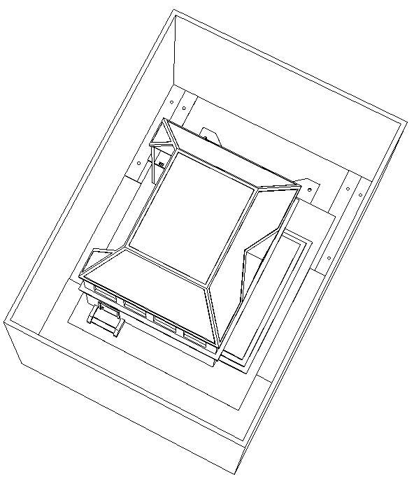
Insert in box and apply label. Seal box and apply label.
Packaging upper house and stand extensions
Tape stand together as shown.
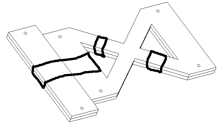
Place the insert in the box bottom for the stand extension. Tape the stand extension down.
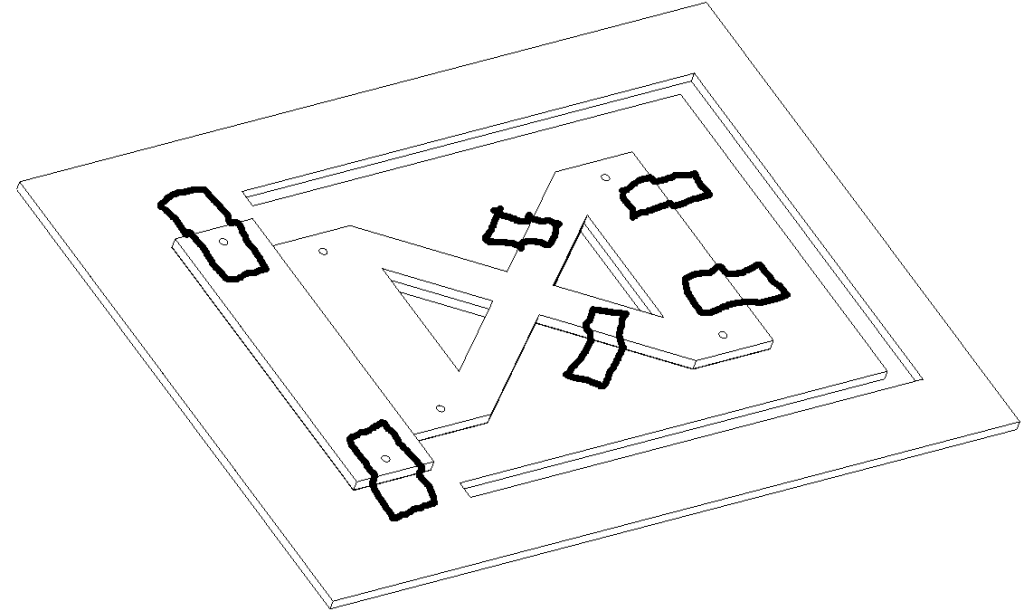
Tape front side of house to lower granite base as shown.
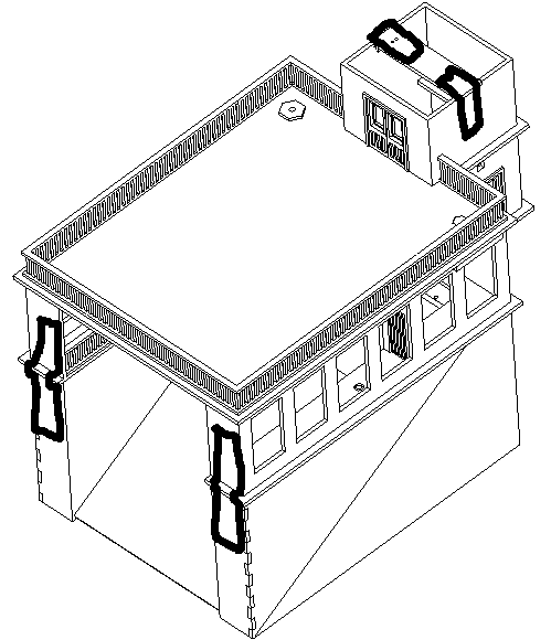
Tape rear side of house as shown. Tape the electrical connector to bottom as shown.
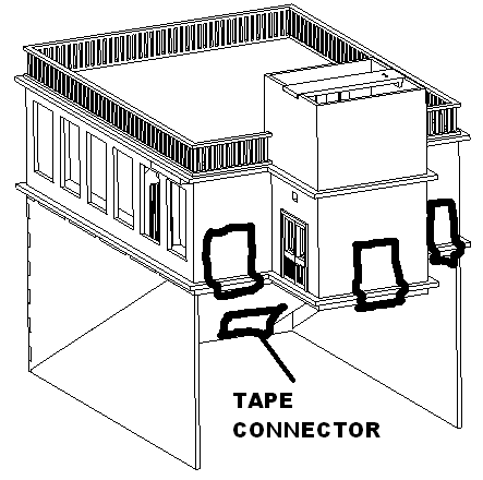
Carefully place house in box.
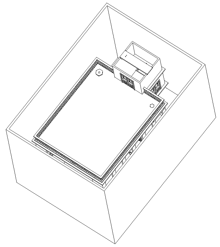
Insert hold downs on top piece.
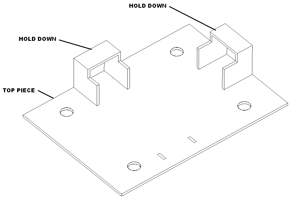
Insert in box and apply label. Seal box and apply label.