
Preassembly
Cut one 3 wire extension to 6″ on female side. Label female side NEOPIXELS. Save male side for other projects.
Cut two 3 wire extension to 6″ on female side. Label female and male side L/R SW and 3/4 SW.
Cut two white 22 gauge wires to 15″ and two grey 22 gauge wires to 15″. Twist white and grey together. Label right speaker and left speaker.
Controller
Bend legs of switch to 90 degrees. Attach switches to switch plate.
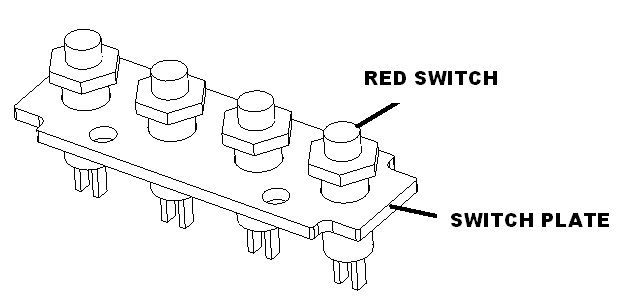
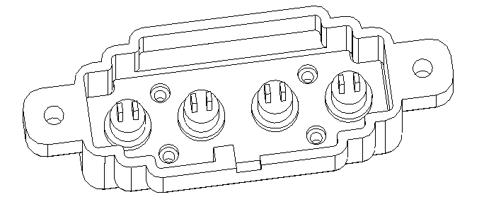
Insert switch plate in controller housing and fasten with 4 M2.3 x 8 screws.
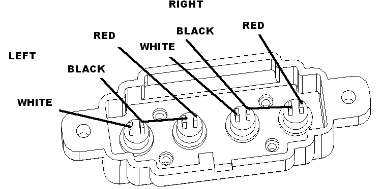
Solder to the terminal as follows route through slot and tywrap down.
Connections to preamp board
Cut a red, black, purple, yellow, green and brown wire to 7.0″ length and twist.
Solder to the I2S preamp board using the following table.
| Connect to | Cable Color |
| VIN | RED |
| GND | BLK |
| MUTE | PUR |
| DIN | YEL |
| LRC/WSEL | GRN |
| BCLK | BRN |
Assembly
Insert brightness button into screen frame as shown.
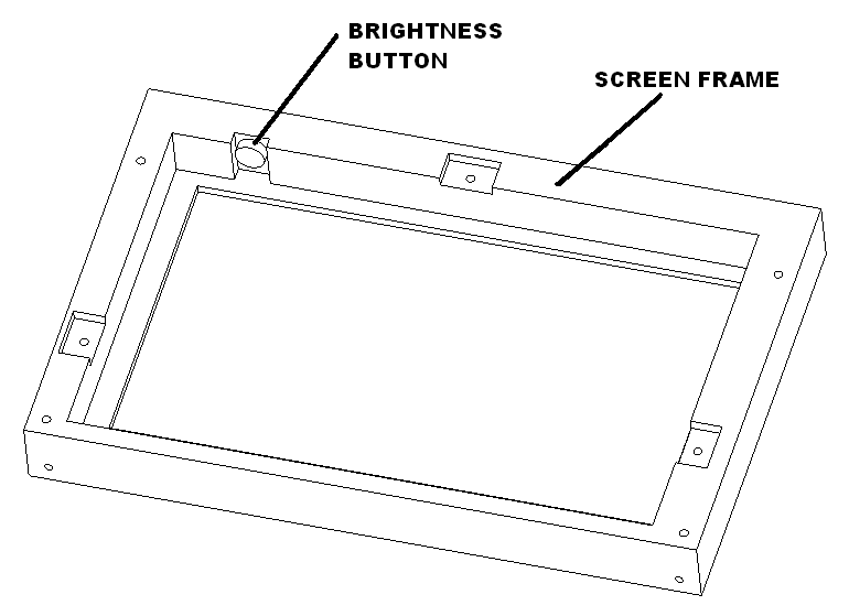
Set screen into bezel. Attach top rubber clamp first with one m2.3×8 screw. Then attach the left and right rubber clamps with two m2.3×8 screws. Screw in four hex standoff to the touchscreen.
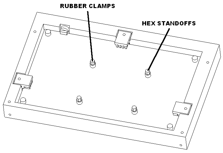
Put the pi imaged microSd card in the pi board.
Mount the pi using the screws supplied. Install the touchscreen flex cable.
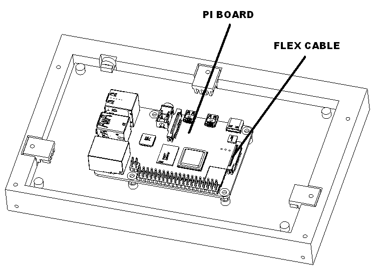
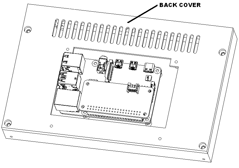
Install back cover with 4 M2.3X8 screws.
Insert the USBC power connector into the drive in bottom base.
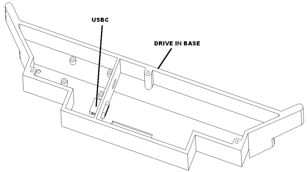
Install I2S preamp board to the drive in base with 4 M2.3×6 pan head screws.
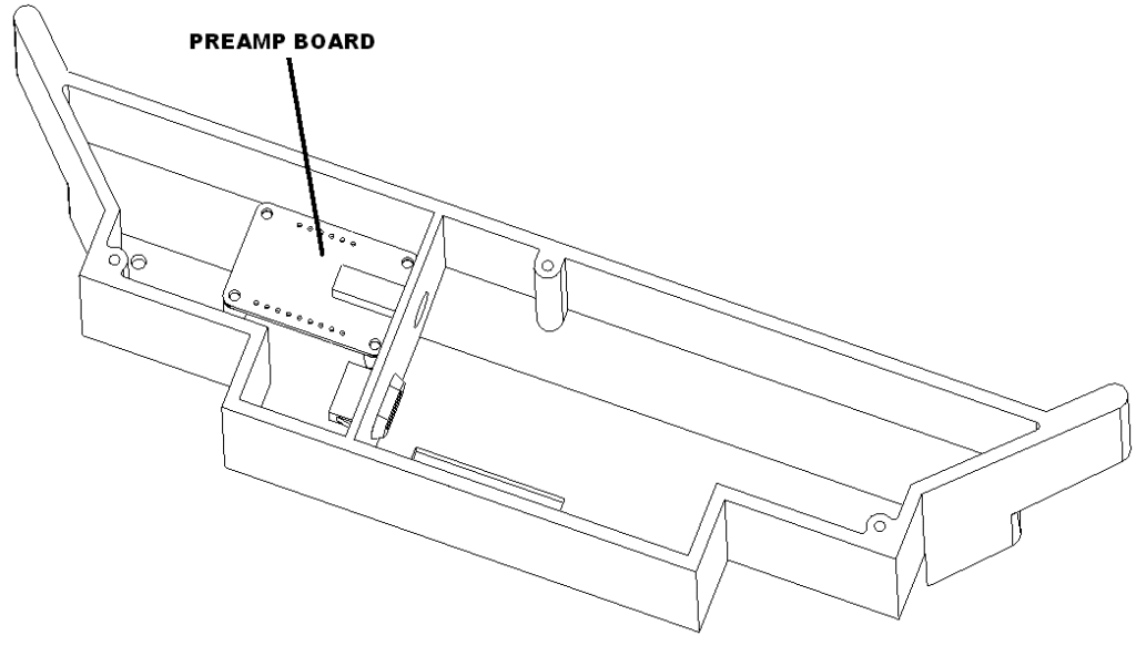
Power supply connection
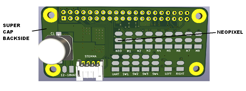
Solder usbc bulkhead connector to super cap pads on back side of the ANPISBC board.
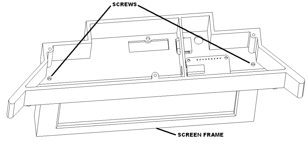
Install the drive in base to the screen frame using 2 M2.3×8 screws.
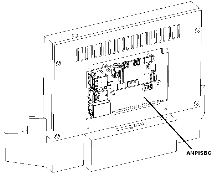
Install the ANPISBC on the pi board.
Speaker connections
Solder the right speaker going to the left terminal and the left speaker going to the right terminal. White is positive gray is negative. Note: The board has the left and right swapped.
Power up test
Power up the animator it should announce that is setting up. Power down if the speakers are working.
Neopixel connections
Solder female NEOPIXELS harness, facing right, to NEO pads. White to ground, red to pin 2 and green to pin 3.
Switch connections
Solder the female SW 3/4 harness, facing right, to SW3, and SW4 as follows. White to SW3 pin 3, and red to SW4 pin 3. Solder the remaining black wire to SW3 ground.
Solder the female SW L/R harness, facing right, to SW1, and SW2 as follows. White to SW1 pin 3, and red to SW2 pin 3. Solder the remaining black wire to SW1 ground.
Preamp connections
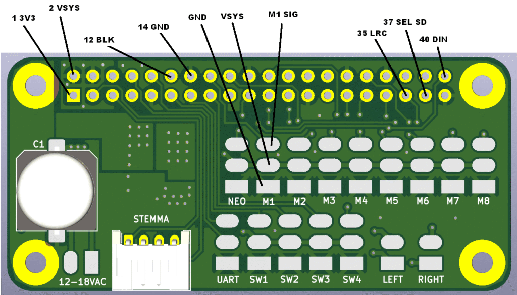
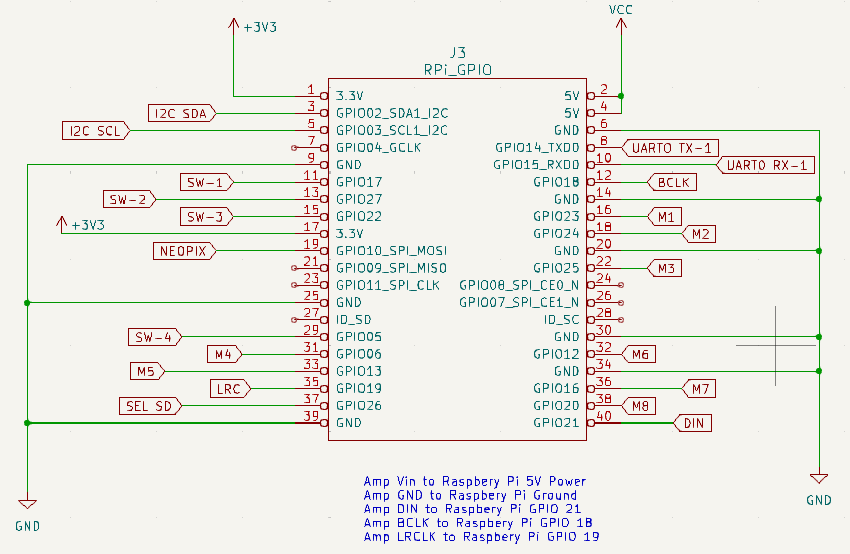
Solder these wires to the ANSPC top side using the following table. Note the pins on the top are 2, 4, 6, 8, 10 … and the pins on the bottom row are 1, 3, 5, 7, 9 …
| Connect to | PIN | Wire Color |
| VSYS | M1 VSYS | RED |
| GND | M1 GND | BLK |
| DIN | 40 | YEL |
| LRC/WSEL | 35 | GRN |
| BCLK | 12 | BRN |
Final assembly
Run all the wires through the hole.
Install usb dongle for portable keyboard. Mark unit and the keyboard with a unique number. Since the dongle and keyboard are tied to each other.
Plug in the pi it should boot and display Jimmy Trains logo. Verify the keyboard is working.
Plug in the 4 button remote and confirm all the buttons work. First button starts the animation, second button pauses, third button volume down, fourth button volume up.
Remove the dongle and install the back cover with 4 M2.3X8 washer head screws.
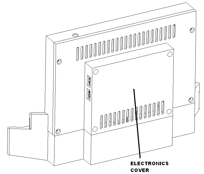
Reinstall the dongle and make sure the keyboard still works.
Clean the screen before packing.
Packaging
Bend the tabs in the mid insert as shown. Tape two speaker and wires to the tabs.
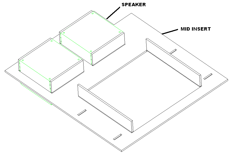
Insert the mid insert into box as shown. Place power supply as shown. Bag the four button switch and tape down to the mid insert as shown.
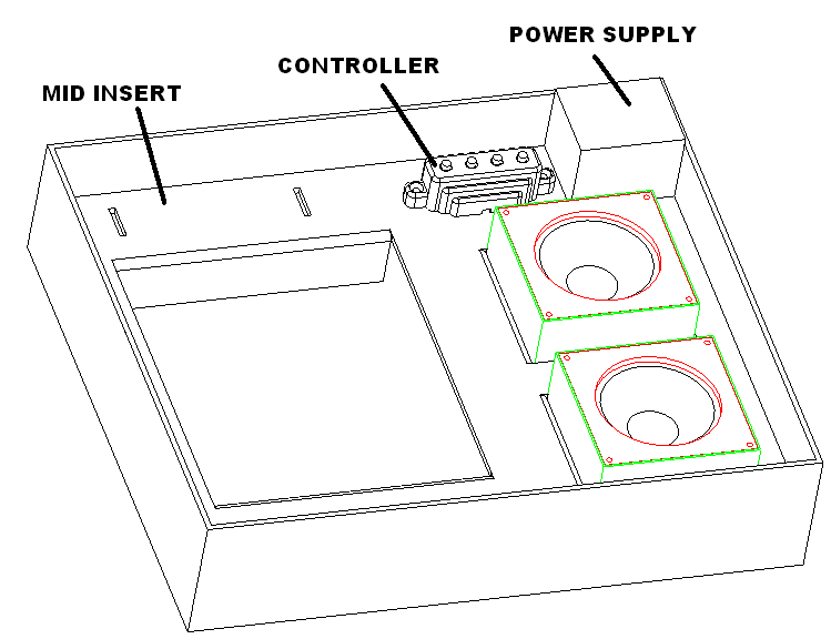
Place the drive in as shown.
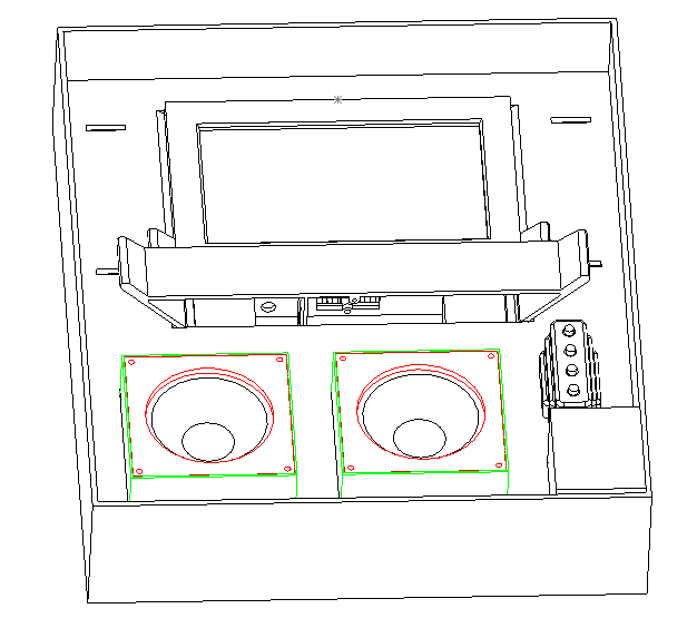
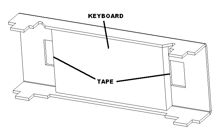
Bend tabs up in presentation insert as shown. Insert keyboard and tape. Insert foam and tape.
Place two templates as shown and insert U in slots of the mid insert.
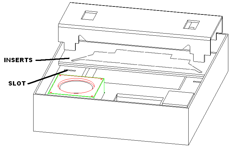
Place presentation label in box and apply inner label.
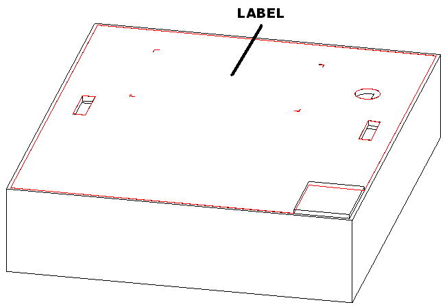
Close box and apply product label.