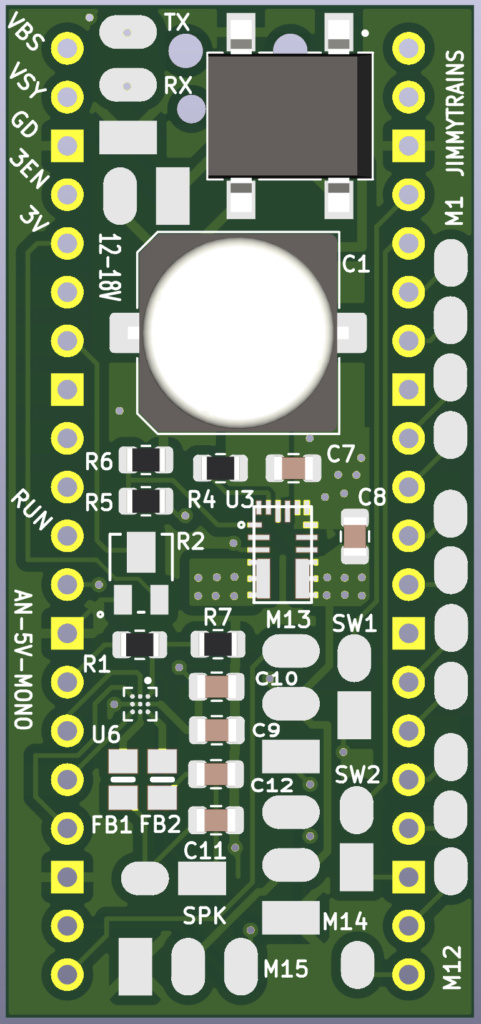
Animator AN-5V-MONO front side
The front side of the animator an-5v-mono board has all the connections for the speaker, servo motors, switches, neopixels, and volume control.
The pi pico is soldered directly to the back of this board using castellated pads on the pico. They become one unit.
The board also has its own 5V power supply so it can be connected directly to a transformer that supplies 12 – 18 volts AC or DC. A separate 5volt microUSB supply can be used instead by plugging that into the pico.
Speaker
Cut two white and two gray 22 gauge wires 10 inches long. Strip and tin.
| Function | Connect to | Wire length/gauge/color/dir |
| Right speaker | SPK | 10″ / 22 / WHT+ GRY-/up |
Solder to the animator using the following table and label “SPK”, attach 3″ from end.
| Connect to | Cable Color |
| GND (SQ pad 1) | GRY |
| Signal (pad 2) | WHT |
Switches
Cut two brown wires 10″ long, solder and shrink wrap to left switch. Label switch wire with “LEFT SW”
Cut two blue wires 10″ long, solder and shrink wrap to right switch. Label switch wire with “RIGHT SW”
| Function | Connect to | Wire length/gauge/color/dir |
| Left switch | SW1 | 10″ / 26 / BRN / up |
| Right switch | SW2 | 10″ / 26 / BLU / up |
Solder to the animator using the following table.
| Connect to | Cable Color |
| GND (SQ pad 1) | BRN / BLU |
| Signal (pad 3) | BRN / BLU |
Servos
Cut female servo harnesses to 3″ lengths. Label female ends with DOOR, ELEVATOR and ROOF.
| Connect to | Wire length/gauge/color/dir |
| M13 (door) | 3″ / 26 / Varies / left |
| M14 (elevator) | 3″ / 26 / Varies / left |
| M15 (roof) | 3″ / 26 / Varies / up |
Solder the cable to the board as shown.
| Pico pins | Connect to | Cable Color |
| GND | GND (SQ pad 1) | BRN |
| +5V | 5V (pad 2) | RED |
| See table above | Signal (pad 3) | YEL |
Pre assembly
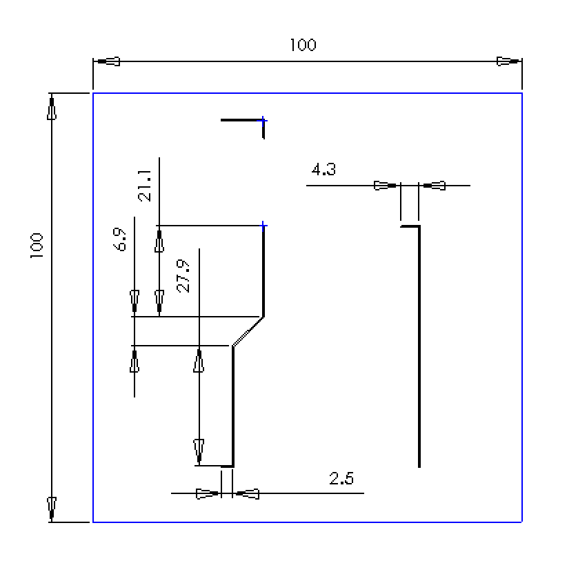
Roof driving rod
Cut and bend .015 inch wire to the dimensions shown below. Set aside.
Fire Neopixel
Cut one red, yellow and black 30 gauge wire. Twist together and cut to 4.5″ lengths.
| Function | Connect to | Wire length/gauge/color/dir |
| Fire Neopixel | M6 | 6″ / 22 / Varies / up |
Cut neopixel strip to 3 lights as shown.
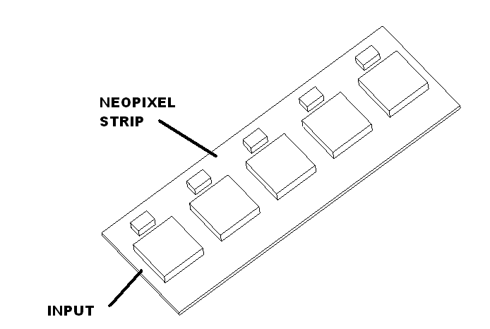
Solder to the input of the LED strip using this table. Set aside.
| Connect to Neopixels | Wire length/gauge/color |
| 5V | 6″ / 30 / RED |
| Signal | 6″ / 30 / YEL |
| GND | 6″ / 30 / BLK |
Room light Neopixel
Cut neopixel strip to one light as shown.
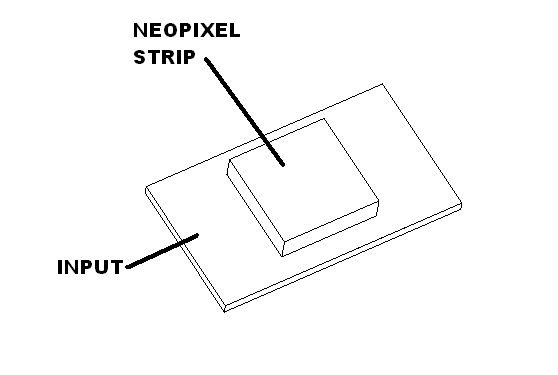
Cut one red, yellow and black 30 gauge wire. Twist together and cut to 4.5″ lengths.
| Function | Connect to | Wire length/gauge/color/dir |
| Fire Neopixel | M1 | 4.5″ / 22 / Varies / up |
| Room Neopixel | M3 | 4.5″ / 22 / Varies / up |
Solder to the input of the neopixel strip using this table.
| Connect to Neopixels | Wire length/gauge/color |
| 5V | 6″ / 30 / RED |
| Signal | 6 ” / 30 / YEL |
| GND | 6″ / 30 / BLK |
Attach room light to out house wall as shown. Run the wire down the wire channel. Set aside.
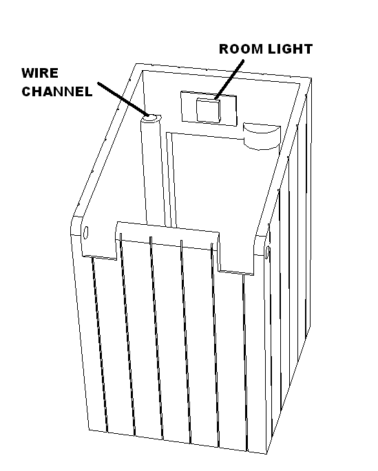
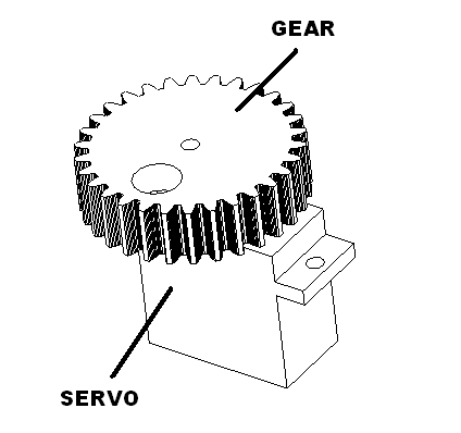
Elevator gear
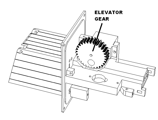
Attach motor to outhouse board to orient it correctly. Apply small amount of glue to inside of spine on gear. Press gear onto servo motor and fasten with the provided screw. Set aside to dry.
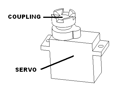
Door coupling
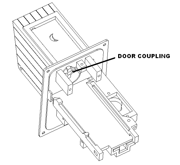
Attach motor to outhouse board to orient it correctly. Apply small amount of glue to inside of spline on coupling. Press coupling onto servo motor and fasten with the provided screw. Set aside to dry.
Assembly
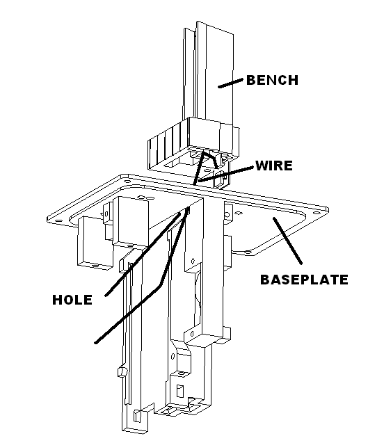
Thread the wires from the neopixel assembly through the bench and through the small hole in the base plate. Fasten with two M2.3 X 8 screws.
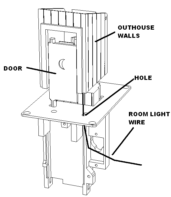
Place the door in the base. Then routing room light wires through the hole in the base. Lower the room walls to the base and attach with three M2.3X 8 screws.
Mount door coupling to door. Put a small mount of glue at the joint and wipe up the excess with a q tip.
Mount elevator servo to chassis with screws supplied as shown.
Attach the roof servo with screws supplied as shown.
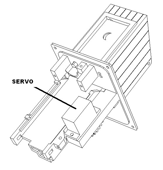
Insert the roof driving rod into slot in base plate. Engauge it into roof and fasten the roof with two m2.3X 8 screws.
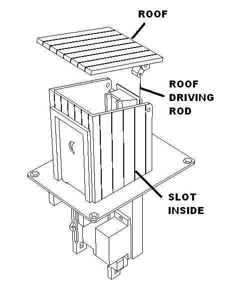
Final connections to animator board
Combine the black wires from the fire and room neopixels and solder to GD.
Combine the red wires from the fire and room neopixel and solder to VSY.
Solder fire neopixels to the animator board using the following table.
| Connect to animator | Wire length/gauge/color |
| M1 Signal | YEL |
Solder room neopixels to the animator board using the following table.
| Connect to animator | Wire length/gauge/color |
| M3 Signal | YEL |
Power up the animator
Plug in the roof servo, elevator servo and door servo into the animator.
Power up the animator. When the animations are now active press the left button to go through the animation sequence. Make sure all the lights work and all the motors turn.
Keep the animator plugged in
Connecting the roof rod to servo
The roof motor in now in the closed position. Cut a servo horn so only two holes are present. Insert the driving rod into the second hole in the horn. Then mount to the motor.
Unplug the animator.
Final assembly
Install the gear cover with two M2.0 X 6 screws as shown. Then route the pot wire in wire channel and then push gear servo wire into the channel.
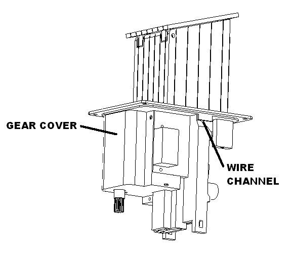
Place the gear servo connector to the left and the door and roof servo connector to the right as shown.
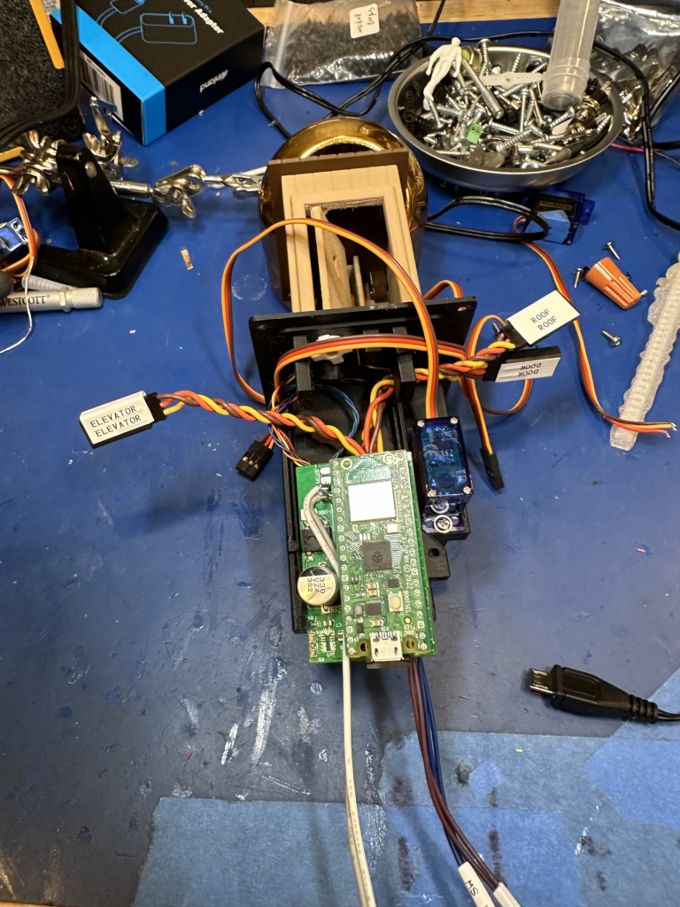
Install the animator onto the chassis. Using an animator clamp and one M2.3 X 6 screw.
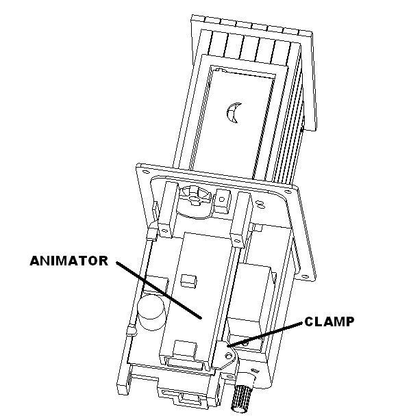
Install the door servo as shown with screws provided. Make sure the door is in the correct position.
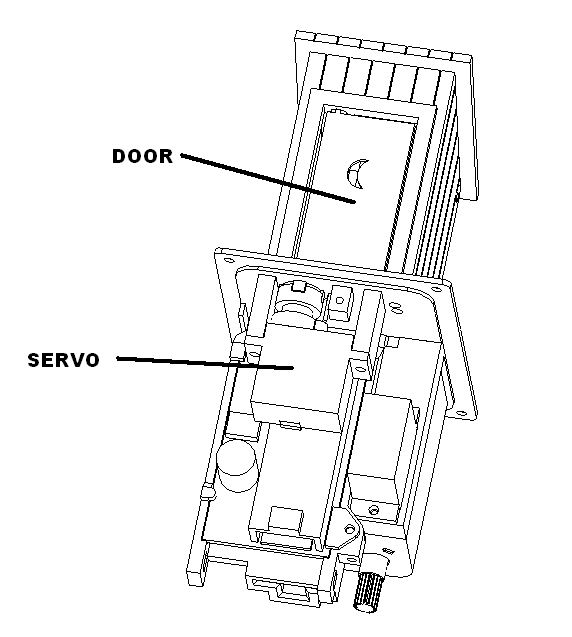
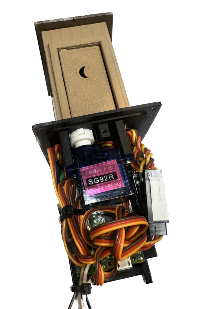
Plug in the elevator and wrap up the wire on the left and tywrap. Plug in the door and roof servos and gather the wires as shown. Tywrap the speaker and switch wires as shown.
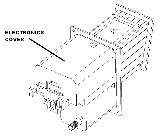
Install the electronics cover with two M2.3X6 screws as shown.
Test and calibration
Plug in the animator and let it go through it initialization sequence. It should announce that is on the network. Open a browser and navigate to animator-outhouse.local. Calibrate the door and roof settings.
Verify all the setting are good by running an animation by pressing the left button.
Packaging
Tape the lower u to the mid insert as shown.
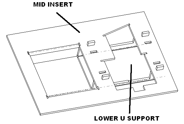
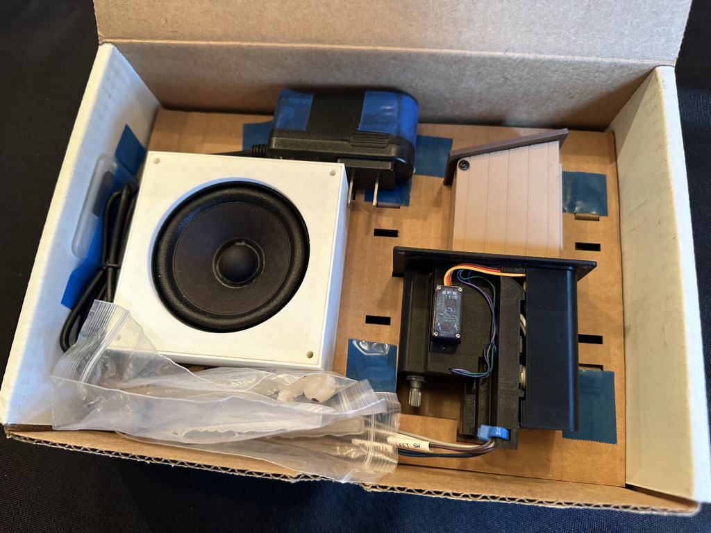
Tape the speaker to the mid insert. Then insert into box. Next place the outhouse in it location. Then tape the microSD card adapter to the left wall. Tape the power supply in. Place the man, woman and alien below the speaker as shown.
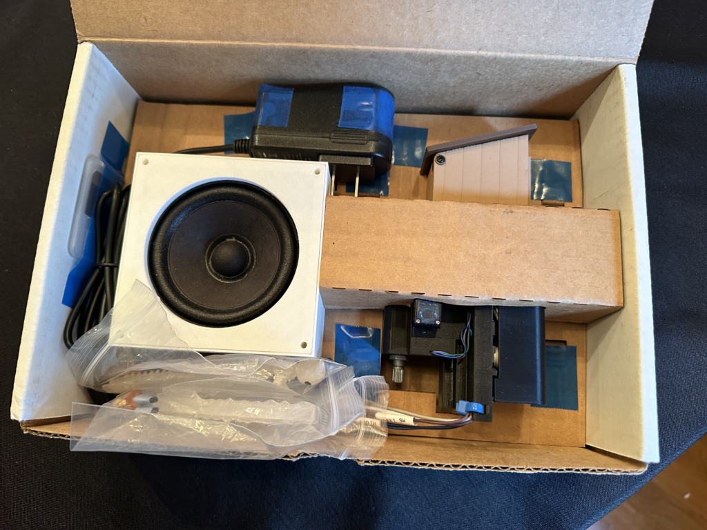
Put the top u insert in.
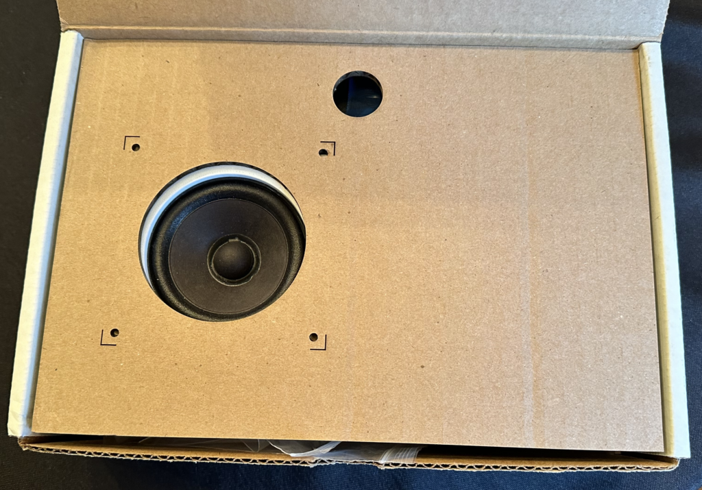
Then put the speaker template in followed by the presentation insert with its label.
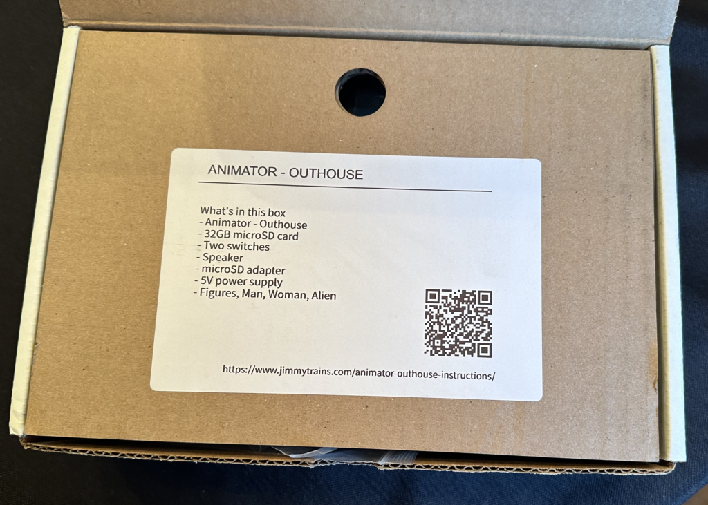
Close the box and apply product label as shown.