
Actuator assembly
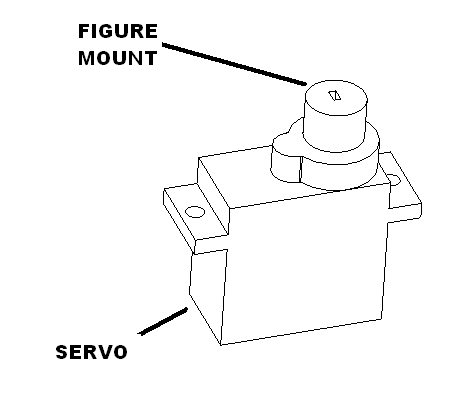
Plug the figure servo into SERVO 2 harness. Power on the AN2S and let it initialize. Press the figure mount oriented as shown.
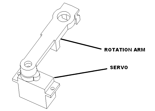
Plug the rotation arm servo into the SERVO 1 harness. Attach the rotation mount to the servo with glue and the screw provided.
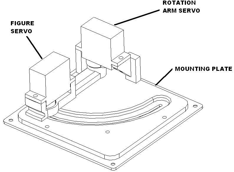
Mount the rotation arm servo to the mounting plate using the screws provides. Repeat with the figure servo.
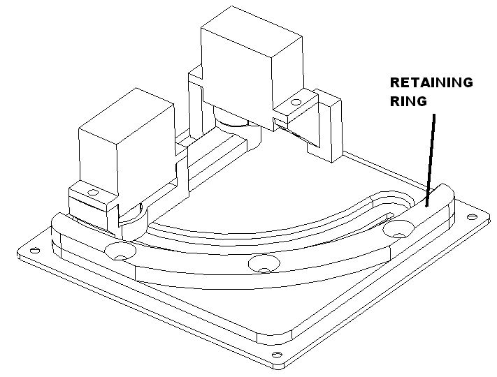
Mount the retaining ring using three M2.3X8 screws as shown.
Program controller assembly
Plug in servo1 and servo2 into the controller.
Hold the pico program button down and plug in the microUSB computer cable. The unit will load into boot loader mode. Copy the circuit python UTF file over to the pico.
Once the pico boots as a circuit python drive delete all the files on the drive and copy the big foot code onto the unit. The unit will boot and initialize to the home position.
Press the “top” button confirm that the “big foot” animation occurs.
Press the “bottom” button confirm that it goes into “program mode”
The controller is now tested. Set aside.
Big foot figure
Cut 0.032in wire and bend as follows.
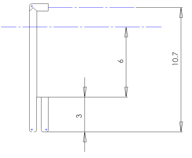
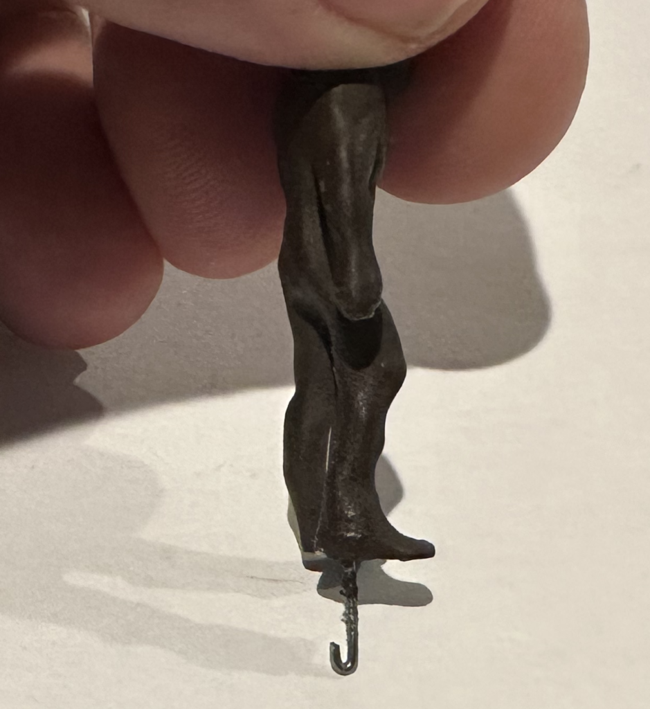
Insert this rod into the figure as shown with the loop end facing rearward. The 90 degree bend help pot the figure in place with glue. Let dry overnight.
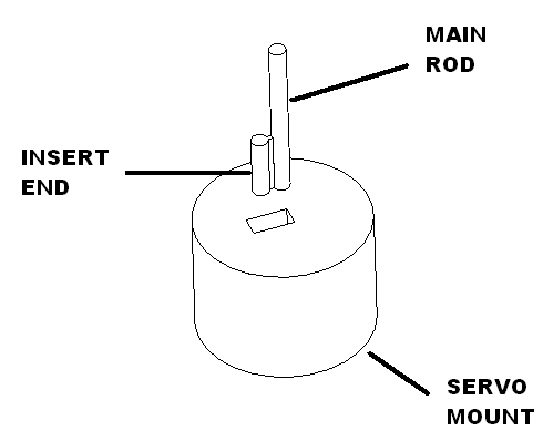
Note: the figure turntable is designed so that the main rod is in the center. The insert end should clear the servo mount. This puts the main rod in the center of the slot.
Paint
Paint figures with brown and black mixed together in equal parts.
Calibrate the control assembly
Get a rotation assembly and controller. Mark them both with a number using removable tape. These items will be packed together.
Plug in servo1 and servo2 into the controller.
Press and hold the “top” button in for “hidden” or the “bottom” button in for “visible” continue holding these buttons and plug in the power supply. Continue holding until you see big foot start to move. Release the button. It should cycle four times at the middle position which indicates that it is in limit adjusting mode. Then it will move to the “home” position.
Insert the figure facing forward.
Press the “top” button to move the figure to the rearward and the “bottom” button to move the figure to the forward.
Once you are satisfied with your adjustment press and hold the “bottom” button until the figure moves forward and backward.
Repeat the above steps for each position.
Unplug the unit and plug in the power supply that will ship with it. Confirm that the platform rotates and does a single cycle.
Unplug everything and the controller rotation assembly and power supply is ready to pack.
Packaging no sound
Put 6 M2.3 X 8 screws in bag. Heat seal.
Put servo mechanism in a bag. Heat seal.
Wrap figure with padding put in bag. Heat seal.
Put controller in bag. Heat seal.
Fold up box, set power supply on right and place controller, servo, spare parts on the bottom. Place figure on top.
Print label and cut and apply instructions on the inside of the lid. Apply product label on the outside of the box.
Packaging with sound
Put 6 M2.3 X 8 screws in bag. Heat seal.
Wrap figure with padding put in bag. Heat seal.
Tape speaker to mid insert as shown.
Tape controller to mid insert as shown.
Gather wires between controller and speaker and tape down.
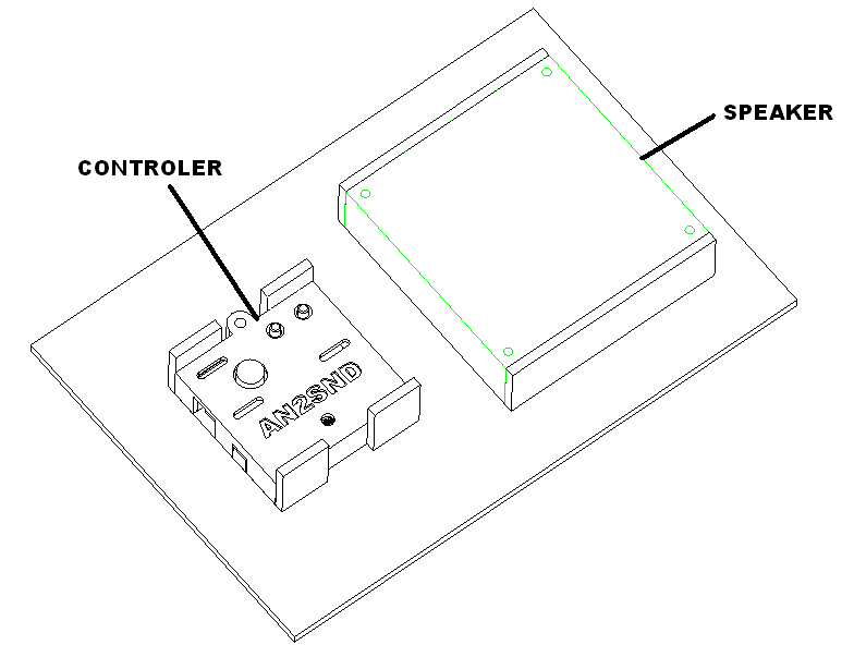
Place mid insert assembly in box.
Place servo mechanism flat side down and tape. Place hiding wall and tape, Place figure on top and tape.
Print inner label apply instructions top insert.
Seal box and apply product label on the outside of the box.