
The boy with kite animation has one servo, and one stepper motor. It uses the animator 5v mono board. The 5v mono board does not have a sd card. Mp3 files are stored directly on the raspberry pi pico flash and outputs left channel sound only.
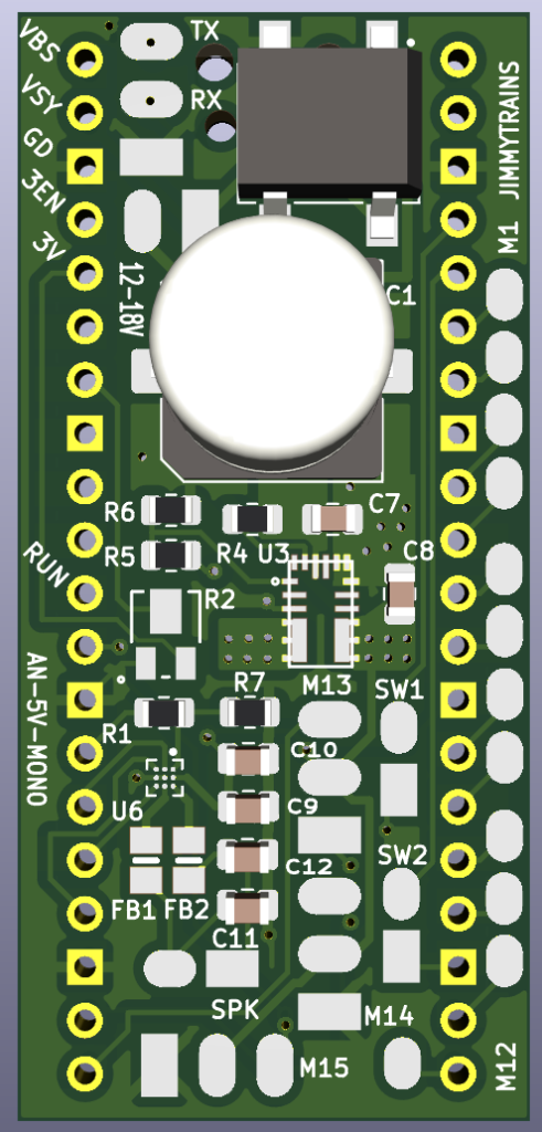
Animator board setup
Put UTF file on new pico using 8.2.10 version. Then when it reboots install the program files on the circuit python drive.
Pre assembly
Snap the speaker cover into the chassis as shown.

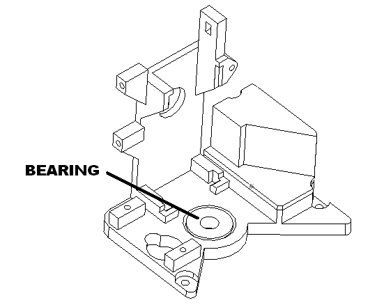
Apply glue to the inside of the bore in the chassis then press the ball bearing into the chassis as shown. Make sure it is even with the top and bottom surface. Set aside to dry.
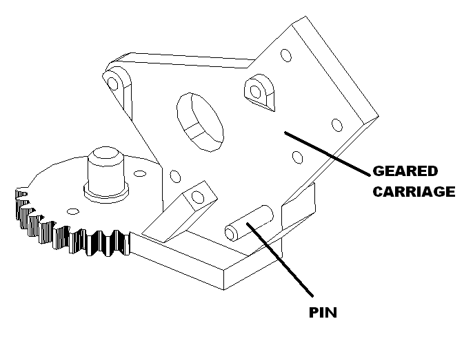
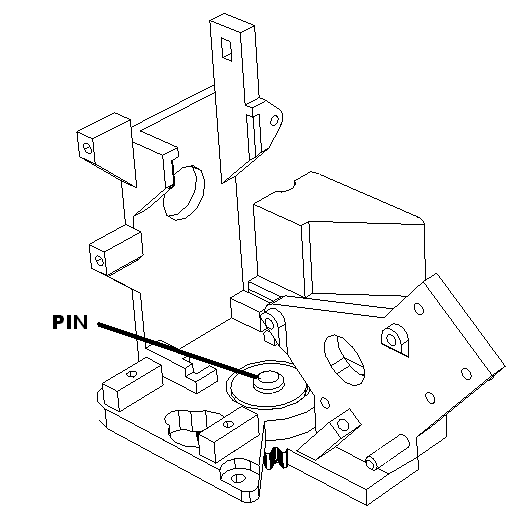
Apply light amount of glue at bottom of pin hole and Insert pin into geared carriage as shown. Set aside to dry.
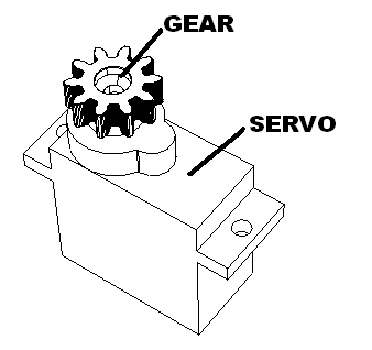
Install gear onto stepper motor as shown.
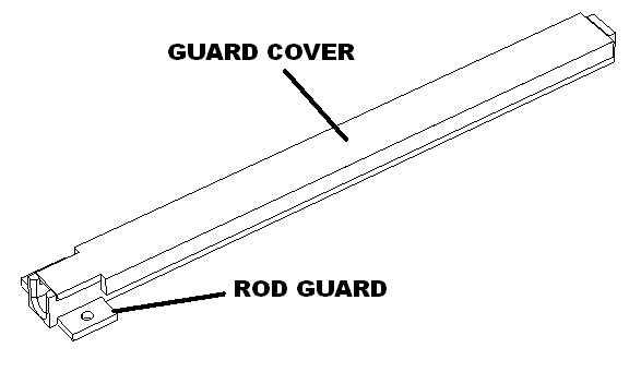
Snap guard over over rod guard.
Apply glue to inside of the bearing in the chassis then insert geared carriage in the chassis. Set aside to dry.
Kite assemlby
Print out kite designs and laser cut them.
Cut 8 wires to 4″ lengths.
Twist red and blue 30 gauge wire as a tail. Cut to 2″. Glue to frame.
Bag and seal four kites and remain wire. This set aside for later packing.
Using red white and blue kite. Glue it to kite frame. Set aside to dry.
Cut .039 wire to 12″. Debur ends.
Animator wiring
Attach the animator board to the kite electrical fixture using one animator clamp and one M2.3 X 6 screw as shown.
Attach the stepper board to the kite electrical fixture chassis using two M2.3 X 6 screws as shown.

Switch connections
Cut two brown 26 gauge gauge wires to 10″ lengths. Solder to a switch then shrink wrap. Repeat for a blue wire. Then solder the switch harnesses to the animator board using the following table.
Then solder the switch harnesses to the animator board using the following table.
| Function | Connect to | Wire length/gauge/color/an dir |
| Left switch | SW1 to pushbutton | 10″ / 26 / BRN / left |
| Right switch | SW2 to pushbutton | 10″ / 26 / BLU / left |
Servo connections
Cut servo female harness to 3″. Then solder the harnesses to the animator board using the following table.
| Function | Connect from then to | Wire length/gauge/color/dir |
| Servo 1 | M14 to Female servo harness | 3″ / 26 / Varies / left |
Power connections
Cut two black 26 gauge gauge wires to 10″ lengths. Then solder to the animator board using the following table.
| Function | Connect to | Wire length/gauge/color/an dir |
| Accessory Power 12-18 V AC/DC | 12-18V | 10″ / 26 / BLK / down |
Stepper board connections
Twist green, blue, yellow, and brown, 30 gauge wire and cut to 4″ lengths. Then solder from the animator board to the back side of the stepper board using the following table.
| Function | Connect from to | Wire length/gauge/color/an dir |
| Stepper coil A1 | M1 to pin 1 Stepper | 4″ / 30 / GRN / left |
| Stepper coil A2 | M2 to pin 2 Stepper | 4″ / 30 / BLU / left |
| Stepper coil B1 | M3 to pin 3 Stepper | 4″ / 30 / YEL / left |
| Stepper coil B2 | M4 to pin 4 Stepper | 4″ / 30 / BRN / left |
Twist black, and red, green 30 gauge wire and cut to 4″ lengths. Then solder from the animator board to the back side of the stepper board using the following table.
| Function | Connect from to | Wire length/gauge/color/an dir |
| Stepper GND | M13 GND to Stepper GND | 4″ / 30 / BLK / left |
| Stepper 5 volts | M13 Vcc to Stepper 5V | 4″ / 30 / RED / left |
Mechanical assembly
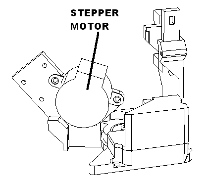
Attach stepper motor to the geared carriage with two M2.6 x 8 screws as shown. Do not fully tighten.
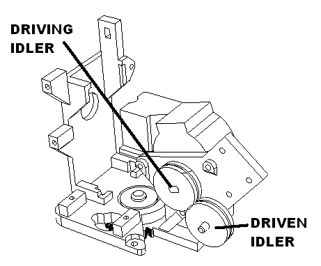
Flip assembly around and install driving idler to the stepper motor shaft and driven idler to the pin. The flanges on both idlers face away from you. Press the driving idler against the driven idler and tighten the stepper mounting screws.
Attach the idler clamp to the geared carriage with two M2.6 x 8 screws as shown.
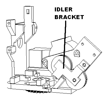
Cut one brown wire and one blue wire to 4″. Then solder wires to speaker as shown.
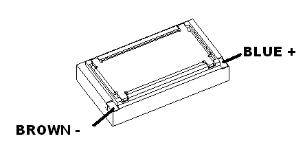
Route speaker wires through speaker wire hole, press speaker in. Set aside.
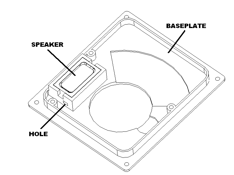
Speaker connections
Route the speaker wires through the chassis and place the chassis on top of the baseplate and attach with three M2.3X 6 screws.
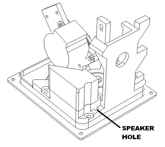
Then solder the speaker to the animator board using the following table.
| Function | Connect to | Wire length/gauge/color/dir |
| Mono speaker | SPK | 4″ / 26 / BRN-BLU+R |
Apply power to servo motor using animator board. It should center. Then attach the servo to the chassis with the geared carrier in the center as shown.
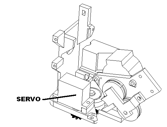
Slide the animator in the slots at the bottom of the chassis. Route all wires under the animator board and fasten it to the chassis using one animator clamp and one M2.3 X 6 screw as shown.
Attach the servo board with two M2.3 X 6 screws as shown.
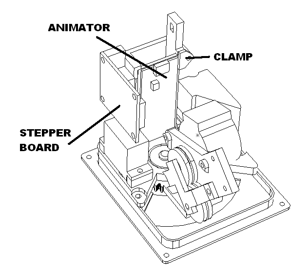
Attach the rod guard to the kite chassis with two M2.6 X 8 screws.
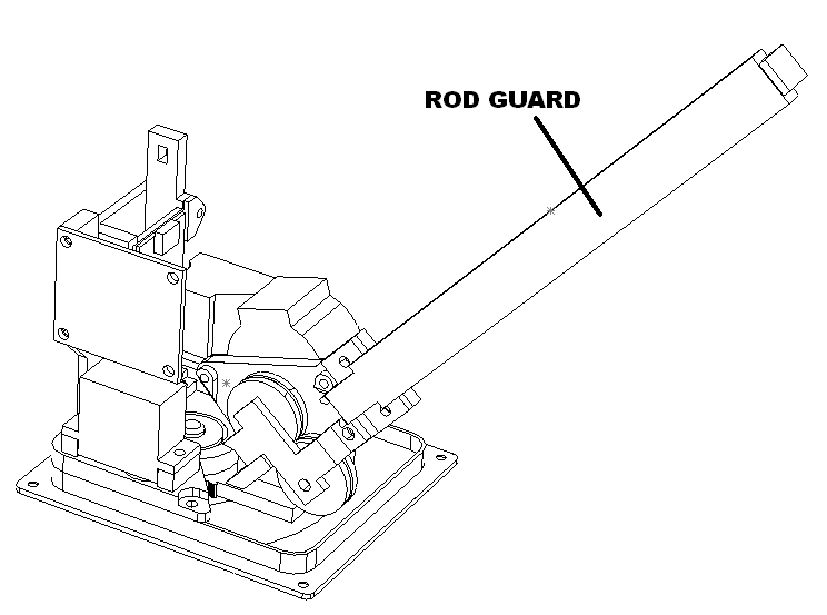
Calibrate kite center position
Using the menu buttons active the carrier center position. Adjust until it is in the center. Press and hold right button until you hear all changes complete.
Package the kite
Laser cut the bottom insert, mid insert, top insert, and presentation insert.
Bent the mid insert as shown.
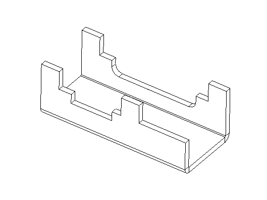
Bend mid insert as shown and Insert bottom insert into the mid insert, fold tabs and tape.
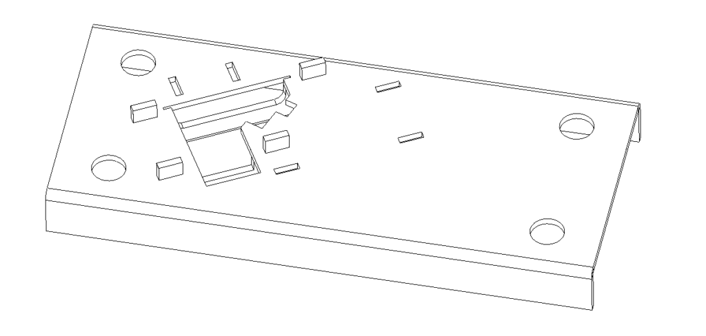
Insert mid insert assembly into the box and then place the kite assembly in it cavity in the mid insert.
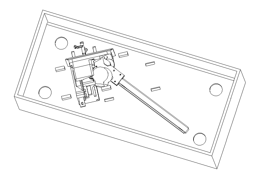
Bend the top insert as shown.
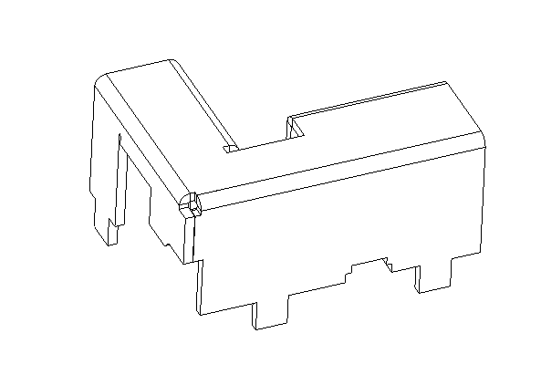
Insert into the slots as shown. Tape the wires down. Tape bag of kites down to the right.
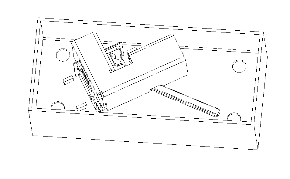
Print out presentation insert label, box label and envelope label. Apply presentation insert label, apply the envelope label.
Put the laser cut kites into the envelope and seal just at the point.
Tye the assembled kite to the bottom of the presentation insert as shown.
Insert the presentation insert place the envelope on top.
Tape the flag rod to box top with two pieces of blue tape.
Close box and apply product label.