
The animator 5v mono board.
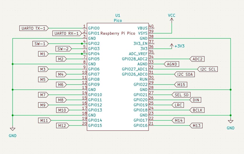
Below is a schematic diagram of what pins on the pico are connected to what pads on the board. Wires are soldered directly to the boards.
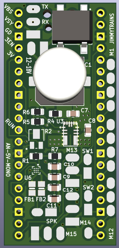
The front side of the board has connections for two switches, 15 servo motors, a mono speaker and accessory power.
Connections Kite
This table has the connections for the boy with kite. It uses a stepper motor and a servo motor.
| Function | Pico pin | Connect to | Wire length/gauge/color/dir |
| Stepper coil A1 | GPIO4 | M1 | 3″ / 26 / Varies / down |
| Stepper coil A2 | GPIO5 | M2 | 3″ / 26 / Varies / down |
| Stepper coil B1 | GPIO6 | M3 | 3″ / 26 / Varies / down |
| Stepper coil B2 | GPIO7 | M4 | 3″ / 26 / Varies / down |
| Servo 1 | GPIO16 | M13 | 3″ / 26 / Varies / down |
| Volume pot | GPIO28 | R2 mounted to board | NA |
| Left switch | GPIO2 | SW1 | 10″ / 26 / BRN / up |
| Right switch | GPIO3 | SW2 | 10″ / 26 / BLU / up |
| Mono speaker | NA | SPK | 10″ / 22 / GRY-WHT+R |
| Accessory Power 12-18 V AC/DC | NA | 12 – 18 V | Note: Connect to transformer only if not using 5v power supply. |